Transcription of Power System Analysis
1 Power System Analysis K. Tomsovic V. Venkatasubramanian School of Electrical Engineering and Computer Science Washington State University Pullman, WA 1. Introduction The interconnected Power System is often referred to as the largest and most complex machine ever built by humankind. This may be hyperbole, but it does emphasize an inherent truth: the complex interdependency of different parts of the System . That is, events in geographically distant parts of the System may interact strongly and in unexpected ways. Power System Analysis is concerned with understanding the operation of the System as a whole.
2 Generally, the System is analyzed either under steady-state operating conditions or under dynamic conditions during disturbances. Electric Power is primarily transmitted as a three phase signal. That is, three AC current currents are sent that are out of phase by 120o but of equal magnitude. Such balanced currents sum to zero and thus, obviate the need for a return line. If the voltages are balanced as well, the total Power transmitted will be constant in time, which is a more efficient use of equipment capacity. For large scale systems Analysis , the assumption is usually made that the System is balanced.
3 Each phase can be then analyzed independently greatly simplifying computations. In the following, the implicit assumption is that three phase systems are being used. 2. Steady-State Analysis In steady state Analysis , any transients from disturbances are assumed to have settled down and the System state is unchanging. Specifically, System load, including transmission System losses, are precisely matched with Power generation so that the System frequency is constant, , 60 Hz in North America. Perhaps, the foremost concern during steady-state is economic operation of the System but reliability is also important as the System must be operated to avoid outages should disturbances occur.
4 The primary Analysis tool for steady-state operation is the so-called Power flow Analysis , where the voltages and Power flow through the System is determined. This Analysis is used for both operation and planning studies and throughout the System at both the high transmission voltages and the lower distribution System voltages. The Power System can be roughly separated into three subcomponents: generation, transmission and distribution, and load. The transmission and distribution network consists of Power transformers, transmission lines, capacitors, reactors and protection devices. The vast majority of generation is produced by synchronous generators.
5 Loads consist of a large number of, and a diverse assortment, of devices, from home appliances and lighting to heavy industrial equipment to sophisticated electronics. As such, modeling the aggregate effect is a challenging problem in Power System Analysis . In the following, the appropriate models for these components in the steady-state are introduced. Modeling Transformers A transformer is a device used to convert voltage levels in an AC circuit. They have numerous uses in Power systems. To begin, it is more efficient to transmit Power at high voltages and low current than low voltage and high current.
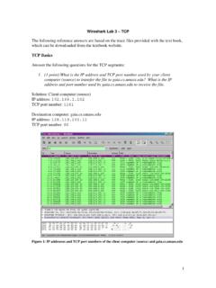
6 Conversely, lower voltages are safer and more economic for end use. Thus, transformers are used to step-up voltages from the generators and then used to step-down the voltage for end use. Another wide use of transformers is for instrumentation so that sensitive equipment can be isolated from the high voltages and currents of the transmission System . Transformers may also be used as means of controlling real Power flow by phase-shifting. Transformers function by the linkage of magnetic flux through a core of ferromagnetic material. Figure illustrates a magnetic core with a single winding. When a current I is supplied to the first set of windings, called the primary windings, a magnetic field, H, will develop and magnetic flux, , will flow in the core.
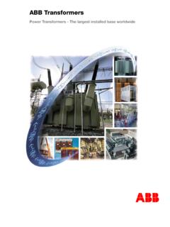
7 Amp re s Law relates the enclosed current to the magnetic field encountered on a closed path. If we assume that H is constant throughout the path then NIHl= ( ) where l is the path length through the core and N is the number of windings on the core so that NI is the enclosed current by the path referred to as the magnetomotive force (mmf). I I Figure a) flux flows through core from first winding, b) flux is linked to a second set of windings The magnetic field is related to the magnetic flux by the properties of the material, specifically, the permeability.
8 If we assume a linear relationship, , neglecting hysteresis and saturation effects, then the flux density B or the flux is lNIHB == or lNIA = ( ) where A is the cross-sectional area of the core. This relationship between the flux flow in the core and the mmf is called the reluctance, R, of the core so that NIR= ( ) Now, if a second set of windings, the secondary windings, is wrapped around the core as shown in Figure , the two currents will be linked by magnetic induction. Assuming that no flux flows outside the core, then the two windings will be see the exact same flux.
9 Since, the two windings also see the same core reluctance, the two mmf s are identical, , 2211 ININ= ( ) If the flux is changing in time, or equivalently the current I, then according to Faraday s Law, a voltage will be induced. Assuming this ideal transformer has no losses, the Power input will be the same as the Power output so 2211 IVIV= ( ) where V1 and V2 are the primary and secondary voltages, respectively. Substituting ( ) and rearranging shows 1212 NNVV= ( ) Thus, the voltage gain in an ideal transformer is simply the ratio of the number of primary and secondary windings.
10 A practical transformer experiences several non-ideal effects. Specifically, these include non-zero winding resistance, finite permeability of the core, eddy currents that flow within the core, hysteresis (the effect arising from the energy required to reorient the magnetic dipoles as the magnetic polarity changes), and magnetic saturation. For steady-state studies of the large System , we desire linear circuit models. These non-ideal effects are typically modeled as a combination of series and parallel impedances in the following way: Series impedances Since the transformer core has a finite permeability, some of the magnetic flux flows outside the core.