Transcription of CHAPTER – 3 ELECTRICAL PROTECTION SYSTEM
1 105 CHAPTER 3 ELECTRICAL PROTECTION SYSTEM DESIGN CONSIDERATION PROTECTION SYSTEM adopted for securing PROTECTION and the PROTECTION scheme the coordinated arrangement of relays and accessories is discussed for the following elements of power SYSTEM . i) Hydro Generators ii) Generator Transformers iii) H. V. Bus bars iv) line PROTECTION and Islanding Primary function of the protective SYSTEM is to detect and isolate all failed or faulted components as quickly as possible, thereby minimizing the disruption to the remainder of the electric SYSTEM .
2 Accordingly the PROTECTION SYSTEM should be dependable (operate when required), secure (not operate unnecessarily), selective (only the minimum number of devices should operate) and as fast as required. Without this primary requirement PROTECTION SYSTEM would be largely ineffective and may even become liability. Reliability of PROTECTION Factors affecting reliability are as follows; i) Quality of relays ii) Component and circuits involved in fault clearance circuit breaker trip and control circuits, instrument transformers iii) Maintenance of PROTECTION equipment iv) Quality of maintenance operating staff Failure records indicate the following order of likelihood of relays failure, breaker, wiring, current transformers, voltage transformers and D C.
3 Battery. Accordingly local and remote back up arrangement are required to be provided. Selectivity Selectivity is required to prevent unnecessary loss of plant and circuits. PROTECTION should be provided in overlapping zones so that no part of the power SYSTEM remains unprotected and faulty zone is disconnected and isolated. Speed Factors affecting fault clearance time and speed of relay is as follows: i) Economic consideration ii) Selectivity iii) SYSTEM stability iv) Equipment damage Sensitivity PROTECTION must be sufficiently sensitive to operate reliably under minimum fault conditions for a fault within its own zone while remaining stable under maximum load or through fault condition.
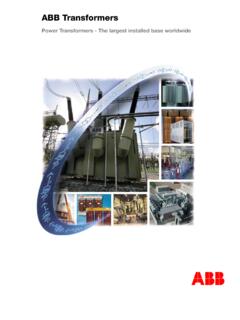
4 PROTECTION Zones Overlapping zones of PROTECTION are provided so that no part of power SYSTEM remains unprotected. The point of connection of the PROTECTION with the power SYSTEM normally defines the zone boundary and generally corresponds to the position of the current transformers. Current transformers if provided on both 106sides of circuit breaker overlap Figure (a). If they are provided on one side blind spots occur Figure (b). Fault between CT and the circuit breaker will not trip the feeder CB and fault current will continue to flow until cleared by back up PROTECTION .
5 Primary and back up PROTECTION The design of a protective SYSTEM should include backup PROTECTION to allow for failures and for periodic maintenance of the interrupting devices, sensing devices, and protective relays. Backup PROTECTION may be either remote or local or it may be a combination of both schemes. Remote backup PROTECTION consists of relays that are set to respond to faults in the next zone of PROTECTION . This type of PROTECTION is relatively slow as it should allow time for the primary relaying in that zone to operate.
6 It also may cause interruption to large portions of the electric supply SYSTEM . In some cases, local backup PROTECTION is justified. Local backup consists of two sets of independent primary PROTECTION and breaker-failure relaying. Ideally, this should include two independent sets of current transformers, voltage transformers, protective relays, and breaker trip coils, but only one breaker-failure relaying SYSTEM is required. Each protective relay SYSTEM should be isolated so that a failure in one will not affect the other. Among other things, this requires that the control power for each SYSTEM be supplied from separate low-voltage circuit breakers or fuses.
7 Two forms of back up PROTECTION are provided. These are PROTECTION failure or circuit breaker failure. Best form of back up PROTECTION for any SYSTEM is one in which both ac and dc supplies are completely separate from main PROTECTION . Economic consideration determines the extent to which back up PROTECTION is provided. Fault Data Protective relay systems measure the current, voltage, or a combination of current and voltage during fault conditions. Fault current magnitude, and the associated change in voltage, varies with the type of fault and with the location of the fault with respect to the sensing devices.
8 GGENERATORPROTECTIONGTRANSFORMERPROTECTI ONBUS ZONEPROTECTIONFEEDER PROTECTION (a) (b) Figure 107 Therefore, a study of the types of faults that can occur is important to ensure that the selected PROTECTION SYSTEM can detect and isolate all faulted portions of the electric SYSTEM . The types of faults that should be considered are three-phase, phase-to-phase, double-phase-to-ground, and single-phase-to-ground. Fault Current Versus Load Current In most cases, fault exceeds normal load current by a factor of 2 or more. However, special consideration should be given to situations where load current is greater than fault current.
9 For example, on systems that are grounded through a neutral impedance, the ground fault current is lower than the normal load current magnitude. For this situation, the use of separate ground fault relaying is required. High-voltage phase over-current devices should not respond to maximum load current because these devices are applied to provide PROTECTION for short-circuits but not for maximum loads. Conductors, transformers, and other current-carrying devices should be rated to carry the maximum expected load, taking into account load profiles, diversity, and short time equipment ratings.
10 Occasionally, special overload PROTECTION is provided for high-voltage equipment, but this should generally be avoided because of the difficulty of coordinating these schemes while maintaining reliable operation of the power SYSTEM . However, overload PROTECTION is required for low-voltage equipment. Circuit-Interrupting Devices Fuses are single phase protective devices that combine sensing and interrupting functions into a single unit. Fuse operation is based on the magnitude and duration of current flowing in each phase of the circuit. The primary application considerations include maximum load, minimum and maximum fault current available, interrupting rating, operating time of the fuse relative to the operating time of protective devices on both the consumer and utility systems, and the effects of single-phase supply due to the operation of one fuse.