Transcription of Power Wheel - Tucker's Machine & Steel Service, Inc ...
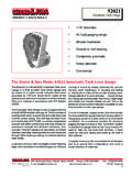
1 1 Power Wheel Planetary Gear DriveModel 102 CONTENTSI ntroduction3 model 10 Wheel Drives - Double Reduction4-5 model 10 Shaft Output Drives - Double Reduction6-7 model 10 Spindle Output Drives - Double Reduction8-9 model 10 Output Shafts and Other Options10 Optional C-Mount Bolt-On Parking Brake11 Lubrication Data11 Warranty Information123 LARGE TAPERED ROLLER BEARINGS ALLOW INCREASED AXIAL AND RADIAL LOADINGDUCTILE IRON HUBSPROVIDE ADDEDSTRENGTH FORRESISTANCETO IMPACTLOADING HEAT TREATEDSPINDLES PROVIDE TOUGHNESSAND INCREASEFATIGUE LIFEBEARING NUT PROVIDES BEARING PRELOAD FOR OPTIMAL BEARING LIFEOPTIMIZEDGEARGEOMETRYINCREASESTHE CONTACTRATIO, WHICHLENGTHENSGEAR LIFESTANDARDDISCONNECTPROVIDESEASE OFTOWINGINTRODUCTIONP ower Wheel Final Drives Auburn Gear is your reliable source for a variety of powertransfer products. This catalog features the model 10 family ofPower Wheel Planetary Gear Drives. Other models of PowerWheels are also available; for a complete offering, contactAuburn also offer planetary gear kits and limited-slip offer you services for design, engineering, prototype supportand full testing and production capabilities.
2 Product applicationsinclude access, agricultural, automotive, construction, forestry,industrial and marine. Auburn Gear offers you quality and reliabil-ity backed by more than 50 years of experience. Greater Design FlexibilityPower Wheel planetary drives allow greater flexibility thanconventional Power train systems and often eliminate the need forcomponents such as drive shafts, axles and chain drives. Themany models and styles offered meet a wide range of mobile andindustrial application requirements. Single, double and triplereduction ratios can be furnished. In addition, they can be sup-plied with a variety of motor mounts and inputs which allow themto be used with most makes of hydraulic motors. High Efficiency and Compact DesignProviding 94 to 98% Power transfer efficiency, Power Wheel planetary drives are significantly more efficient than many othertypes of drives, including differential design planetaries.
3 Therugged, compact design of these drives saves space and pro-vides for long service models can be furnished with parking brakes. Auburn Gearhas designed integral parking brakes in Models 5, 6, 6B, 7, 8 , 8 Band 9. These units provide a very compact planetary drive/parking brake package which is particularly useful in applicationswhere space is limited. Responsive PerformancePower Wheel drives deliver the Power you require for smoothoperation and precise control. These units are also fully revers-ible. Reverse Power is easily obtained by reversing rotation of theinput. For vehicle applications, the positive traction provided byindividually powered wheels results in superior maneuverabilityand improved ground clearance than conventional drive Gear Power Wheel drives can be an efficient solutionfor any application where you need to increase torque or reducespeed to achieve usable Power . Let Power Wheel planetarydrives help you put Power in its 10 FEATURES4 Preferred Centerof Wheel or ( )Oil Fill orDrain PlugOutputRotationOpposite toInput Rotation12.
4 75 ( ) -16 UNF 2B HolesEqually Spaced on ( ) C2 .625-11 UNC 2B Thru Holeson ( ) Dia. and4 .50-13 UNC 2B Thru Holeson ( ) ( ) - ( - )SAE C PILOT / ( / ).53 ( ) - ( - ) ( )OPTIONAL:12 .625 ( )-11 UNC ( ) Deep Holes Equally Spacedon ( ) Disk Brake Installation12 . ( )Thru Holes Equally Spacedon ( ) ( ).67 ( ).89 ( ) ( ) ( ) ( ) ( ) Min. ( ) "( )Max. intermittent output torque1 180,000 lb-in (20,340Nm)Max. input speed .. 5,000 RPMA pproximate Weight .. 400 lbs ( kg)Oil capacity .. 150 oz (4,435 cc)1 Depending on the duty cycle and the nature of the application, a normal continuous output torque of 1/3 to 1/2 of the maximum Intermittent should yield satisfactoryPower Wheel life. Customer testing and application analysis is strongly given in: INCHES (mm) model 10 Wheel Drives -Double Reduction Power WheelGENERAL SPECIFICATIONSNON-POWERED UNITS ARE ALSO AVAILABLE - Contact Auburn Gear for InformationOPTIONAL PARKING BRAKES ARE ALSO AVAILABLE (See Page 11) O Ring or Gasket required (not supplied by Auburn Gear) O Ring Size: SAE C 2-159 For Lubrication Data, see Page 115 BEARING LOAD, LIFE AND SPEED RELATIONSHIPSSF x RR LF =R= Allowable resultant load for givenlocation from mounting flangeR = Anticipated load at location frommounting flangeLF= Life Factor from table (see below)SF= Speed Factor from table (see below)OUTPUTBEARINGSPEEDHOURS(RPM)SFLFB- 10 : The same torsional loading constraints usedin the driving mode must be used in the braking modewhen braking through the Power Wheel drive gear :The data presented in this catalog is forgeneral information and preliminary layoutpurposes only.
5 Auburn Gear, through itspolicy of continual improvement, reserves theright to update its products; therefore, theinformation presented is subject to specific application and/or dimensionalinformation, contact Auburn INDICATES REGULAR VOLUME PRODUCED ITEMS WITH BEST CHART: model 10 Wheel DRIVES -DOUBLE REDUCTIONOPTIONSMOTORPILOT/HUBINPUTSPLIN ERATIOOPTIONSWHEELSTUDSSPECIALFEATURESDE SCRIPTIONSAE C14T. 12 :1 NONE3/4 x Disc HolesBoot SealQuick DisconnectPipe Plugs Spindle SideHigh Strength Carrier0W2C14161926364452011 DHZQPYMAKE ALL SELECTIONSWITHIN ONE COLUMNORDERCODES Std. USE OPTION ORDER CODESTO BUILD ORDER NUMBERS elect desired characteristics from chart, note correct order codes,and order using sample format shown at right: 0W2C 14360Z0W2C 14 36 0 ZAWAY FROM SPINDLEMOUNTING FLANGE45,00040,00035,00030,00025,00020,0 0015,00010,0005,000 ALLOWABLE RADIAL LOAD LB. (KG.)-5-4-3-2-1123456 DISTANCE FROM MOUNTING FACETO RADIAL LOAD (INCHES) MOUNTING FLANGENOTE:These curves are supplied as a design guide andapply to resultant radial load only.
6 They indicatethe importance of maintaining Wheel positionover the bearing actual analysis, applications should be re-viewed by Auburn Gear Engineering using datasupplied on Application Data A A2: SAE B: SAE C C2: Dim. A (See ShaftOutput Optionson Page 10) ( ) + Dim. A ( ) + Dim. A ( ) + Dim. A ( )9 SAE A A2: .31 ( )*SAE B: .41 ( )SAE C C2: .53 ( ) ( )SAE A1, C1 - ( - ) Dia. Thru Holes 12 Holes, Equally ( )Oil Fill orDrain PlugsOil Fill orDrain PlugSEE MOUNTING CHART(Shown: SAE C, C1, C2)Oil LevelCheck ( ) ( ( ) ( ) ( ) ( ) ( ) ( )SAE A, B, ( ) 11 UNC-2B Thd. ( ) Full Thd. 20 Holes, Equally SpacedSAE A2, C2:.531 ( ) Dia. Thru Holes 20 Holes, Equally ( ) Spotface - .06 ( ) DeepSAE A1, C1 SAE A, A2, B, C, C2 OUTPUTROTATIONSAME ASINPUTROTATION*Spacer plate required when :1 ratio is usedwith any A mount and the 14T input adds .600 ( ) to overall length of driveDim. A (See ShaftOutput Optionson Page 10) model 10 Shaft Output Drives -Double Reduction Power Wheel1 Depending on the duty cycle and the nature of the application, a normal continuous output torque of 1/3 to 1/2 of the Maximum Intermittent should yield satisfactoryPower Wheel life.)
7 Customer testing and application analysis is strongly given in: INCHES (mm)GENERAL SPECIFICATIONSMax. intermittent output torque1 180,000 lb-in (20,340 Nm)Max. input speed .. 5,000 RPMA pproximate Weight .. 300 lbs (136 kg)Oil capacity .. 150 oz (4,435 cc)For Lubrication Data, see Page 11 OPTIONAL PARKING BRAKES ARE ALSO AVAILABLE (See Page 11)7 NOTE:These curves are supplied as a design guide andapply to resultant radial load only. They indicatethe importance of maintaining Wheel positionover the bearing actual analysis, applications should be re-viewed by Auburn Gear Engineering using datasupplied on Application Data LOAD, LIFE AND SPEED RELATIONSHIPSSF x RR LF =R= Allowable resultant load for givenlocation from mounting flangeR = Anticipated load at location frommounting flangeLF= Life Factor from table (see below)SF= Speed Factor from table (see below)OUTPUTBEARINGSPEEDHOURS(RPM)SFLFB- 10 : The same torsional loading constraints usedin the driving mode must be used in the braking modewhen braking through the Power Wheel drive gear :The data presented in this catalog is forgeneral information and preliminary layoutpurposes only.
8 Auburn Gear, through itspolicy of continual improvement, reserves theright to update its products; therefore, theinformation presented is subject to specific application and/or dimensionalinformation, contact Auburn INDICATES REGULAR VOLUME PRODUCED ITEMS WITH BEST CHART: model 10 SHAFT OUTPUTDRIVES - DOUBLE REDUCTIONOPTIONSMOTORPILOT/HUBINPUTSPLIN ERATIOOPTIONSOUTPUTSHAFTSSPECIALFEATURES DESCRIPTIONSAE AA1A2 SAE BSAE CC1C213T. - 16/3214T. - 12 :1 :1*20T - 8/1623T - 8 KeyedGrease Cavity**High Strength Carrier0SA0SA10SA20SB0SC0SC10SC213141720 273745522023K2 VYUSE OPTION ORDER CODESTO BUILD ORDER NUMBERORDERCODESS elect desired characteristics from chart, note correct order codes,and order using sample format shown at right:MAKE ALL SELECTIONSWITHIN ONE COLUMN OSB135220 V 0SB 13 52 20 V*Spacer plate required when :1 ratio is used with any A mountand the 14T input spline.**For Vertical Shaft Up OperationMOTOR MOUNTING CHART: O RING OR GASKET REQUIRED (Not Supplied by Auburn Gear) O RING SIZES: SAE A 2 042, SAE B 2 155, SAE C 2 159 PILOT DIAMETER - ( - ) - ( - ) - ( - )MOTOR MOUNTING HOLE DIMENSIONSSAE A, A1, A2(2).
9 500 ( ) -13 UNC -2B Holes Equally Spaced on ( ) B. B(2) .500 ( ) -13 UNC -2B Holes Equally Spaced on ( ) B. (4) .500 ( ) -13 UNC -2B Holes Equally Spaced on ( ) B. C, C1, C2(2) .625 ( ) -11 UNC -2B Holes ( ) Deep on ( ) B. (4) .500 ( ) -13 UNC -2B Holes .90 ( ) Deep on ( ) B. SHAFT END35000(15873)30000(13605)25000(11338)2 0000(9070)15000(6803)10000(4535)5000(226 8)0 ALLOWABLE RADIAL LOAD LB. (KG)BEARING LIFEBEARING LIFE CURVEBASED ON LIFE = 3000 SPEED = 100 RPM OUTPUTFLANGEMOUNTING FACEMAX. LOADSAE A, A2, B, C, C2 = ( )SAE A1, C1 = .69 ( )876 5432 10( ) ( ) ( ) ( ) ( ) ( ) ( ) ( ) ( )DISTANCE FROM MOUNTING FACE TO RADIAL LOAD IN (MM)8 SAE A, A1, A2: SAE B: SAE C C2: ( ) ( ) ( ) ( )9 SAE A, A1, A2: .31 ( )*SAE B: .41 ( )SAE C C2: .53 ( ) ( )SAE A1, C1:.847 - .850 ( - ) Dia. Thru Holes 12 Holes, Equally ( )Oil Fill orDrain PlugsSEE MOUNTING CHART(Shown: SAE C, C1, C2)Oil LevelCheck ( ) ( ) ( ) ( ) ( ) ( ) ( ) ( )SAE A, B, C.
10 625 ( ) 11 UNC-2B Thd. ( ) Min. Full Thd. 20 Holes, Equally SpacedA2, C2:.531 ( ) Thru Holes 20 Holes, Equally ( ) Spotface .06 ( ) DeepSAE A1, C1 SAE A, A2, B, C, C2 OUTPUTROTATIONSAME ASINPUTROTATION12 ( ) 16 UNF Thd. Thru HolesEqually Spaced on ( ) *Spacer plate required when :1 ratio is used with any A mount and the 14T input adds .600 ( ) to overall length of ( ).89( ) ( ) ( )OPTIONAL PARKING BRAKES ARE ALSO AVAILABLE (See Page 11) Power WheelDimensions given in: INCHES (mm)GENERAL SPECIFICATIONSMax. intermittent output torque1 180,000 lb-in (20,340 Nm)Max. input speed .. 5,000 RPMA pproximate Weight .. 380 lbs (172 kg)Oil capacity .. 150 oz (4,435 cc)For Lubrication Data, see Page 111 Depending on the duty cycle and the nature of the application, a normal continuous output torque of 1/3 to 1/2 of the maximum Intermittent should yield satisfactoryPower Wheel life. Customer testing and application analysis is strongly 10 Spindle Output Drives -Double Reduction9 NOTE:These curves are supplied as a design guide andapply to resultant radial load only.


