Transcription of PowerLogic Circuit Monitor - Contemporary Controls
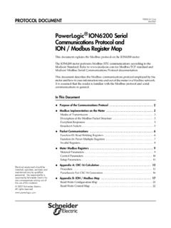
1 Retain for future Circuit MonitorSeries 4000 Reference Manual(Includes Models 4000, 4250, 4000T)Instruction Bulletin63230-300-212B112/2005 2005 Schneider Electric All Rights ReservedHAZARD CATEGORIES AND SPECIAL SYMBOLSRead these instructions carefully and look at the equipment to become familiar with the device before trying to install, operate, service or maintain it. The following special messages may appear throughout this bulletin or on the equipment to warn of potential hazards or to call attention to information that clarifies or simplifies a addition of either symbol to a Danger or Warning safety label indicates that an electrical hazard exists which will result in personal injury if the instructions are not is the safety alert symbol.
2 It is used to alert you to potential personal injury hazards. Obey all safety messages that follow this symbol to avoid possible injury or : Provides additional information to clarify or simplify a NOTEE lectrical equipment should be installed, operated, serviced, and maintained only by qualified personnel. No responsibility is assumed by Schneider Electric for any consequences arising out of the use of this NOTICEThis equipment has been tested and found to comply with the limits for a Class A digital device, pursuant to part 15 of the FCC Rules.
3 These limits are designed to provide reasonable protection against harmful interference when the equipment is operated in a commercial environment. This equipment generates, uses, and can radiate radio frequency energy and, if not installed and used in accordance with the instruction manual, may cause harmful interference to radio communications. Operation of this equipment in a residential area is likely to cause harmful interference in which case the user will be required to correct the interference at his own expense. This Class A digital apparatus complies with Canadian indicates an imminently hazardous situation which, if not avoided, will result in death or serious indicates a potentially hazardous situation which, if not avoided, can result in death or serious indicates a potentially hazardous situation which, if not avoided, can result in minor or moderate , used without the safety alert symbol, indicates a potentially hazardous situation which, if not avoided.
4 Can result in property PowerLogic Circuit Monitor Series 4000 Reference Manual12/2005 Table of Contents 2005 Schneider Electric All Rights ReservediCHAPTER 1:INTRODUCTIONC ircuit Monitor Description .. 1 Accessories and Options for the Circuit Monitor .. 1 Features .. 3 Topics Not Covered in This Bulletin .. 4 CHAPTER 2:SAFETY PRECAUTIONSB efore You Begin .. 5 CHAPTER 3: OPERATIONO perating the Display .. 7 Viewing the Screen .. 7 How the Buttons Work .. 7 Display Menu Conventions .. 8 Selecting a Menu Option .. 8 Changing a Value.
5 8 Cycling Screens on the Display .. 9 Main Menu Overview .. 10 Configuring the Circuit Monitor using the Setup Menu .. 11 Setting Up the Display .. 11 Setting Up the Communications .. 12 Setting the Device Address .. 12RS-485, RS-232, and Infrared Port Communications Setup .. 12 Ethernet Communications Card (ECC) Setup .. 13 Redirecting the Port .. 14 Redirecting the IR Port to the ECC Subnet .. 14 Redirecting the RS-232 Port to the ECC 15 Redirecting the RS-232 to the RS-485 Port .. 16 Redirecting the IR Port of the Display to the RS-485.
6 17 Setting Up the Metering Functions of the Circuit Monitor .. 17 Setting Up Alarms .. 19 Setpoint Learning .. 20 Creating a New Custom Alarm .. 21 Setting Up and Editing 22 Setting Up I/Os .. 25 Selecting I/O Modules for the IOX .. 25 Configuring I/O Modules for the IOX .. 27 Configuring I/O Modules for the IOC .. 28 Setting Up Passwords .. 31 Advanced Setup Features .. 32 Creating Custom Quantities to be 32 Creating Custom Screens .. 35 Viewing Custom Screens .. 39 Advanced Meter Setup .. 39 Resetting Min/Max, Demand, and Energy Values.
7 41 Viewing Metered Data .. 42 Viewing Metered Data from the Meters Menu .. 43 Viewing Minimum and Maximum Values from the Min/Max Menu .. 43 Viewing Alarms .. 45 Viewing Active Alarms .. 46 Viewing and Acknowledging High Priority Alarms .. 46 Viewing I/O Status .. 47 Harmonic Values .. 47 Reading and Writing Registers .. 48 Performing a Wiring Error Test .. 49 Running the Diagnostics Wiring Error Test .. 50 PowerLogic Circuit Monitor Series 4000 Reference Manual 63230-300-212B1 Table of Contents12/2005 2005 Schneider Electric All Rights ReservediiCHAPTER 4:METERING CAPABILITIESReal-Time Readings.
8 55 Min/Max Values for Real-Time Readings .. 56 Power Factor Min/Max Conventions .. 57 VAR Sign Conventions .. 58 Demand Readings .. 59 Demand Power Calculation Methods .. 59 Block Interval 60 Synchronized 62 Demand Current .. 62 Demand Voltage .. 62 Thermal Demand .. 63 Predicted Demand .. 63 Peak Demand .. 64 Generic Demand .. 64 Input Metering Demand .. 65 Energy Readings .. 66 Power Analysis Values .. 68 Harmonic Power .. 70 CHAPTER 5:INPUT/OUTPUT CAPABILITIESI/O Options .. 71 Digital Inputs .. 71 Demand Synch Pulse Input.
9 72 Analog Inputs .. 73 Analog Input Example .. 74 Relay Output Operating Modes .. 75 Mechanical Relay Outputs .. 77 Setpoint-Controlled Relay Functions .. 78 Solid-State KYZ Pulse Output .. 782-Wire Pulse Initiator .. 793-Wire Pulse Initiator .. 79 Calculating the Kilowatthour-Per-Pulse Value .. 80 Analog Outputs .. 81 Analog Output Example .. 82 CHAPTER 6:ALARMSA bout Alarms .. 83 Alarms Groups .. 83 Setpoint-Driven Alarms .. 84 Priorities .. 85 Alarm Levels .. 85 Custom Alarms .. 86 Setpoint-Controlled Relay Functions.
10 86 Types of Setpoint-Controlled Relay Functions .. 87 Scale Factors .. 89 Scaling Alarm Setpoints .. 90 Alarm Conditions and Alarm Numbers .. 91 Waveshape Alarm .. 97 Threshold .. 98 Upper Limit .. 98 Using Waveshape Alarms .. 99 CHAPTER 7:LOGGINGA bout Logs .. 101 Alarm Log .. 101 Alarm Log Storage .. 101 Data Logs .. 101 Alarm-Driven Data Log Entries .. 102 Organizing Data Log Files .. 102 Data Log Storage .. 10263230-300-212B1 PowerLogic Circuit Monitor Series 4000 Reference Manual12/2005 Table of Contents 2005 Schneider Electric All Rights ReservediiiMin/Max Logs.
