Transcription of Prepreg thickness chart - Advanced Circuits
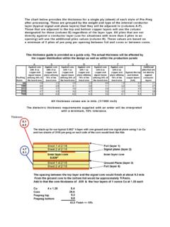
1 Asheetincontactwithcoppercoverageinexces sof50% (layer1) (layer2) " (layer3) (layer4) +/-10% thickness values are in mils. (1/1000 inch)The dielectric thickness requirements supplied with an order will be interpreted with a minimum, 10% chart below provides the thickness for a single ply (sheet) of each style of Pre-Preg after processing. These are grouped by the weight and type of the internal conductor layer (typical signal and plane layers) that they will be adjacent to (columns A-F). Those that are adjacent to the top and bottom copper layers will use the column designated for these (column G) regardless of the layer type.
2 All plies that are not directly against a conductor layer (use for situations with more than 2 plies in an opening) will use the additional plies values (column H). These values are based on a minimum of 2 plies of pre-preg per opening between foil and cores or between stack-up for our typical 4 layer with one ground and one signal plane using 1 oz Cu and two sheets of 2116 pre-preg on each side of the core would look like thisThis thickness guide is provided as a guide only. The actual thickness will be affected by the copper distribution within the design as well as within the production panelsThicknessFinish +/- 10% A B C D E F G HPre-PregStylesAgainst core with.
3 5 oz copper and signal traces utilizing 30% of the board areaAgainst core with .5 oz copper and plane utilizing 70% of the board areaAgainst core with 1 oz copper and signal traces utilizing 30% of the board areaAgainst core with 1 oz copper and plane utilizing 70% of the board areaAgainst core with 2 oz copper and signal traces utilizing 30% of the board areaAgainst core with 2 oz copper and plane utilizing 70% of the board areaAgainst the top and bottom copper layers (foil).Additionalplies that are not directly