Transcription of Pressure Regulator - Cat Pumps
1 Pressure RegulatorStandard Models 7001-7033 Lower Body SS Measure Metric MeasureMODELS 7001, 7002, 7003 AND .100 Flow Range .. GPM ( l/m) Pressure Range (7001) ..100-1000 PSI (7-70 bar) (7002) ..500-2000 PSI (35-140 bar) (7003) ..1500-3000 PSI (105-210 bar)Max. Temperature ..240 F (116 C)Inlet/Outlet Port ..3/8 NPTF (3/8 NPTF)By-Pass Port ..1/2 NPTF (1/2 NPTF)Weight .. lbs. ( kg)Dimensions .. x (159 x 38 mm)MODELS 7011, 7012, 7013, 7014 AND .100 Flow Range .. GPM ( l/m) Pressure Range (7011) ..100-1000 PSI (7-70 bar) (7012) ..500-2000 PSI (35-140 bar) (7013) ..1500-3000 PSI (105-210 bar) (7014) ..2000-4000 PSI (140-275 bar)Max. Temperature ..240 F (116 C)Inlet/Outlet Port ..1/2 NPTF (1/2 NPTF)By-Pass Port ..3/4 NPTF (3/4 NPTF)Weight .. lbs. ( kg)Dimensions .. x (191 x 48 mm)MODELS 7021, 7022, 7023, 7024 AND .100 Flow Range .. GPM ( l/m) Pressure Range (7021) ..100-1000 PSI (7-70 bar) (7022) ..500-2000 PSI (35-140 bar) (7023).
2 1500-3000 PSI (105-210 bar) (7024) ..2000-4000 PSI (140-275 bar)Max. Temperature ..240 F (116 C)Inlet/Outlet Port ..3/4 NPTF (3/4 NPTF)By-Pass Port ..1 NPTF (1 NPTF)Weight .. lbs. ( kg)Dimensions .. x (216 x 57 mm)MODELS 7031*, 7032, 7033 AND .100 Flow Range .. GPM ( l/m) Pressure Range (7031) ..250-1000 PSI (18-70 bar) (7032) ..1000-2000 PSI (70-140 bar) (7033) ..1500-3000 PSI (105-210 bar)Max. Temperature ..240 F (116 C)Inlet/Outlet Port ..3/4 NPTF (3/4 NPTF)By-Pass Port ..1 NPTF (1 NPTF)Weight .. lbs. ( kg)Dimensions .. x (216 x 57 mm)* Model 7031 replaces model Conical piston and seat provide a consistently smooth flow that reduces wear and compensates for Pressure spikes for extended valve life. l Lightweight flow-through design for easy Unique high velocity design assures consistent Pressure for multiple pump or shut-off gun Maintains full Pressure while running in idle for quick return to system Piston retainer and lower body are 316SS for added compatibility on the.
3 100 Standard FPM elastomers for compatibility with many liquids and temperatures up to 240 Adjusting nut allows easy calibrated Pressure Multiple regulators can be installed in parallel to handle larger High Pressure Systems require a primary Pressure regulating device ( Regulator , unloader) and a secondary Pressure relief device ( pop-off valve, relief valve). Failure to install such relief devices could result in personal injury or damage to pump or property. CAT Pumps does not assume any liability or responsibility for the operation of a customer s high Pressure all CAUTIONS and WARNINGS before commencing service or operation of any high Pressure system. The CAUTIONS and WARNINGS are included in each service manual and with each Accessory Data sheet. CAUTIONS and WARNINGS can also be viewed online at or can be requested directly from CAT Pumps . SELECTIONThis Pressure Regulator is designed for systems with single or multiple Pumps , solenoid (gate) valves, nozzles, and standard or weep : For multiple pump systems, it is best to use a Pressure Regulator not a Pressure sensitive regulating Regulator should meet both the desired system flow (combined nozzle flow rate requirement) and the desired system : Operation below the minimum flow of the Regulator causes the Regulator to cycle or chatter.
4 Operation above the maximum flows of the Regulator causes premature Regulator wear, Regulator cycling and prevents attaining desired system Regulator operates properly when mounted in any direction; however, it is preferred to keep the plumbing to a minimum and the Pressure adjusting nut easily accessible. The best mounting location is directly on the pump discharge manifold head. Flexible, high Pressure hose (minimum single wire braid) should be at least the size of the Regulator ports when plumbing to and from the this is a flow through design Regulator , the inlet and discharge connections are interchangeable and are located on the sides. An arrow on the label indicates liquid flow in either direction. Port size varies with each size of Regulator (see specifications). Plumb into one side for inlet flow from pump and plumb opposite side to the discharge line with spray guns, solenoid (gate) valves or by-pass connection of this Regulator is located on the bottom.
5 An arrow on the label indicates the direction of flow. Port size varies with each size of Regulator (see specifications). By-pass liquid is directed out this port and can be routed to a reservoir (preferred method), or to a drain or back to the pump Pressure Regulator maintains established system Pressure in the discharge line and at the pump head when the trigger gun is closed or solenoid (gate) valve is closed or the nozzle is clogged, thus by-passing all unrequired flow. Squeezing the trigger gun or opening the solenoid (gate) valve allows for a quick return to established system Pressure without ADJUSTMENT1. Setting and adjusting the Regulator Pressure must be done with the system on .2. Start the system with Regulator backed off to the lowest Pressure setting (counterclockwise direction).3. Squeeze the trigger and read the Pressure on the gauge at the : Do not read the Pressure at the gun or If more Pressure is desired, release the trigger, turn brass adjusting nut one quarter turn in clockwise Squeeze the trigger and read the Repeat this process until desired system Pressure is Once the desired system Pressure is reached, stop turning the brass adjusting : A minimum by-pass flow of 5% of the Regulator rated flow capacity is required for proper Regulator performance.
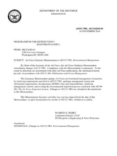
6 If the entire output is directed through the Regulator (zero by-pass) the cushioning feature of the by-pass liquid is eliminated and the Regulator can malfunction or wear If desired system Pressure cannot be reached, review TROUBLESHOOTING When servicing existing systems, back off adjusting Follow adjustment procedures as stated : Do not adjust regulators Pressure setting to compensate for a worn nozzle. Check the nozzle as part of the regular maintenance and replace if : A secondary Pressure safety relief device ( pop-off valve, safety valve) should be used along with this Pressure Regulator . Final adjustment for the relief valve should relieve at 200 psi above the system operating Regulator INSTALLATION1 Pressure Gauge2 Relief Valve Shown as a secondary safety relief valve3 Pulsation Dampener4 Pressure Regulator5 Triplex Plunger Pump2 DISCHARGE1435 INLETBY-PASSRead all CAUTIONS and WARNINGS before commencing service or operation of any high- Pressure systemSERVICINGCAUTION: Before commencing with service, shut off drive (electric motor, gas or diesel engine) and turn off water supply to pump.
7 Relieve all discharge line Pressure by triggering gun or opening valve in discharge Disconnect by-pass, discharge and inlet plumbing from Remove Regulator from Secure lower body of Regulator in a vise with brass adjusting nut facing Remove upper body by unthreading from lower Grasp top of piston stem and separate from conical Remove piston stem with stack of spring washers, flat washers and anti-rotating washer and place on flat Remove conical piston with reverse pliers by making contact on the inside diameter of conical : Exercise extreme caution to avoid contact and damage to outside diameter and sharp tip of conical Remove piston retainer from lower body of : Exercise extreme caution to avoid contact and damage to the inside diameter of the piston Remove conical seat from lower body of : Exercise extreme caution to avoid contact and damage to outside diameter and the tapered surface of the : With the Regulator completely disassembled, inspect lower body sealing areas where the conical seat and piston retainer makes contact for grooves, pitting and wear.
8 If damage is found, replace with new lower body or complete new Regulator . If not, proceed with : Conical piston and seat should be changed as a matched set when upgrading from the old tapered piston and seat. See Tech Bulletin : Spring washers and flat washers should be changed as a spring set. See Tech Bulletin Place lower Regulator body with by-pass port facing down into a Lubricate and install o-ring onto outside diameter of conical seat. Press conical seat down into lower Regulator body with small hole facing Lubricate and install o-ring onto piston retainer. Press piston retainer with raised surface facing Lubricate and install back-up-ring, then o-ring onto outside diameter of conical piston. Press conical piston with sharp point down into piston Replace piston stem with stack of spring washers and flat washers into hole of conical Place anti-rotating washer on top of spring set. Align tabs on washer with slots on the upper : The number of flat washers varies with each spring set.
9 Place the first flat washer between the anti-rotating washer and spring stack. Place second washer (if required) between spring stack and retaining ring. Place all remaining washers with first Thread upper body into lower Re-install Regulator onto Reconnect by-pass, discharge and inlet plumbing to Proceed to Pressure all CAUTIONS and WARNINGS before commencing service or operation of any high- Pressure systemTROUBLESHOOTING Cycling/Chattering l Too little flow for valve specifications. l Air in system, poor connections. l Inlet seals in pump worn. l O-ring in gun worn. System will not l Nozzle worn. build up to Pressure l Improper nozzle size for system specs. l Foreign material trapped in seat. Pressure drop l Nozzles worn. l Piston and seat in Regulator worn. l Air in system, poor connections. l Insufficient flow to pump. l Filter clogged. Check and clean regularly. l Fatigued or broken spring washers. Pressure spikes l Minimum by-pass of 5% not present.
10 While in by-pass l Excessive Pressure adjustment made for worn nozzle. REPLACE NOZZLE. Reset system Pressure . Leakage from l O-ring around piston worn. Service with O-ring Kit. Regulator vent hole l Piston Retainer scored. Service with O-ring kit and or top slots replace retainer. l Fatigued or broken spring washers. Approximate Gauge Gauge Pressure Reading Between Between at Gauge Pump/Unloader Unloader/Gun-Nozzle-Valve System in operation system Pressure system Pressure (gun open) System in by-pass 200-300 PSI above 200-300 PSI above (gun closed) system Pressure system pressurePRESSURE READINGCUTAWAYEXPLODED VIEW(Models 7001, 7002, 7003 shown)StandardFPMO-Rings for maximum durability and top adjusting nut for setting and adjusting system inline mounting for compact easy leaking from weep hole signals worn O-Rings and needed 316SS seat and piston for long life and thousands of cycles. Item Description MATL 7001 7002 7003 7011 7012 7013 7014 7021 7022 7023 7024 7031 7032 7033 401 Nut, Adjusting BB 30758 30758 30758 30759 30759 30759 30759 30760 30760 30760 30760 30760 30760 30760 405 Washer, Anti-Rot STL 34491 34491 34491 34492 34492 34492 34492 34493 34493 34493 34493 34493 34493 34493 406 Body, Upper STNP 408 Spring Set STL 76201 76202 76202 76211 76212 76213 76214 76221 76222 76223 76224 76221 76222 76223 410 Retainer, Piston SSS 30873 30873 30874 30875 30875 30876 30876 30877 30877 30878 30878 30877 30877 30878 Retainer, Piston (.)