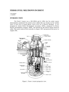
Transcription of PRESSURIZED WATER REACTORS - mragheb.com
1 Chapter 2 PRESSURIZED WATER REACTORS M. Ragheb 3/19/2015 INTRODUCTION In a PRESSURIZED WATER Reactor (PWR), the coolant is PRESSURIZED to about 2,200 psia using a pressurizer and is not allowed to boil. The PRESSURIZED WATER is then pumped to steam generators where steam is produced and then fed to the turbine plant for the production of electricity. The reactor vessel and the associated steam generators, pressurizer, and coolant pumps are enclosed in a containment structure. Figure1. Ohi power station complex, operated by Kansai Electric Power Inc., Japan. Figure 2. Schematic of a PWR fission reactor showing the core, control rods, coolant pumps and steam generators inside the containment structure.
2 Notice the size of the standard man on the right hand side. REACTORS of this type were originally developed for naval propulsion purposes, and then adapted to land-based applications with larger sizes and lower fuel enrichment from the 98 w/o in naval systems to the w/o level, which is about four times that of natural uranium at percent. Ordinary WATER has a double function as coolant and moderator. The cycle efficiency of a PWR is about 32 percent. Its capital cost is low, however, since it operates at a high power density reaching 100 MWth/m3. POWER LOOP For reliability considerations a minimum of two and sometimes as many as four steam generators and main coolant pumps are used as shown in Fig.
3 3. In a typical PWR circuit shown in Fig. 4, WATER at about 2200 psia or 150 bars is pumped into a pressure vessel containing the reactor core shown. The WATER flows through an annular region between the reactor vessel and the reactor core and then its flow is distributed by a nozzle system to the core for cooling the fuel elements. The reactor coolant pumps move the coolant to the steam generators, where steam is produced and then fed to the turbine plant. The coolant is condensed in a condenser then fed by the feedwater pumps back to the steam generators. The condenser uses a source of WATER such a coolant pond or lake, river, ocean or cooling towers as heat sinks.
4 Figure 3. For reliability considerations a minimum of two and sometimes as many as four steam generators and main coolant pumps are used in a PWR. Figure 4. Typical PWR circuit. REACTOR VESSEL High pressure WATER at a pressure of about 2250 psia enters four inlet nozzles located above the midpoint of the pressure vessel as shown in Figs. 5 and 6. Figure 5. PWR reactor vessel showing the core, control rods, and coolant flow. The WATER flows downward through the annular space enclosed by the reactor vessel and a thermal shield, and then upward through the fuel assemblies. WATER exits from the fuel assemblies to the upper plenum, and then down around the inside of the upper pressure vessel and out of the four outlet nozzles shown in Fig.
5 6. Figure 6. Cutout view of PWR reactor pressure vessel showing the core, fuel channels, control rods, and instrumentation. The core contains instrumentation channels and grid spacing for the fuel elements. Some elements have spider shaped conduits through them for the control rods. A core support shield and a core barrel support the core. The latter hangs from the seal ledge near the closure head. Some gamma rays attenuation is provide by the core barrel to supplement the shielding provided by the thermal shields, a non-load bearing component. The thermal shields function is to reduce to gamma rays heating in the reactor vessel wall. They also contribute to neutron shielding of the reactor vessel to prevent its embrittlement through radiation damage by neutron irradiation.
6 Pressure vessels are forged from a 600 ton steel ingot. Steel scrap is heated in an electric furnace to 2,000 degrees Celsius or 3,600 degrees Fahrenheit. Then each of five giant ladles is filled with 120 tons of the orange hot molten metal. Argon gas is injected to eliminate impurities, and manganese, chromium and nickel are added to make the steel harder. The mixture is poured into a blackened casing to form ingots meters wide in the rough shape of a cylinder. Five times over three weeks, the ingots are pressed, reheated and re-pressed under 15,000 tons applied by a machine that rotates them gradually, making the floor tremble as it works. The heavy forging is needed to make the steel uniformly strong by aligning the crystal lattices of atoms that make up the metal, known as the grain.
7 In a casting, they would be randomly jumbled. The process is partly art and partly science similar to the making of Samurai swords. This single ingot technique is used by the Japan Steel Works (JSW) Company in Japan. Another alternative is to turn back the technological clock and weld together two smaller forgings that are then welded using explosive techniques. That technique was used over the past 40 years in the USA and France and is still applied in China. To prevent corrosion, the interior of the 600 ton and 12 inch thick vessel is lined with a stainless steel cladding. REACTOR CORE AND FUEL The core shown in Figs. 5 and 6 has a diameter of about 12 feet. It consists of about 200 fuel assemblies with a square cross section approximately inches on the side.
8 A fuel assembly is shown in Fig. 7. In a typical fuel assembly, the fuel rods are arranged in a 17 by 17 or 16 by 16 square array. About one third of the fuel assemblies contain control rods which are incorporated into them by control rod guide tubes which replace the fuel rods. Other rods within the fuel assemblies contain no fuel and are filled instead by in core instrumentation and burnable poisons such as boron which extend the core life. The fuel consists of uranium dioxide UO2 pellets with an enrichment ranging between to percent in U235. These pellets are inch in diameter and inch in length. The pellets are enclosed in a Zircalloy-4 cladding tube with a wall thickness of inch.
9 Zircalloy is used because of its low neutron absorption helping the neutron economy in the PWR. The fabrication process leaves a radial clearance between the cladding and the fuel pellets of about inch. Figure 7. PWR fuel assembly with control rod drive. Figure 8. Temperature distribution in UO2 fuel element and cladding. OPERATIONAL CHARACTERISTICS Table 1 shows the typical operational characteristics of a PWR, and Fig. 9 shows a typical PWR flow diagram. Table 1. Operational Characteristics of a typical PWR. Characteristic Value Thermal Power output 3,800 MWth System pressure 2,250 psia Fuel enrichment Coolant flow lbs/hr Inlet temperature 565 oF Outlet temperature oF Maximum fuel temperature 3,420 oF Average linear heat rate kW/ft Maximum linear heat rate kW/ft Average heat flux 206,000 BTU/( ) Maximum heat flux 550,000 BTU/( ) Minimum Departure from Nucleate Boiling ratio (DNBR)
10 Active height 150 inches Equivalent active diameter inches Height to diameter ratio Active core volume 1413 ft3 Average core power density 2,690 kW/ft3 Fuel weight 103,000 kgs Specific power kW/kg U Burnup 33,000 Mwdays/MTU Conversion ratio Number of fuel assemblies 241 Fuel element array 16x16 Assembly dimensions 8 in X 8 in Number of fuel rods per assembly 236 Total number of fuel rods 56,876 Fuel element pitch in Fuel element outer diameter in Pitch to diameter ratio Cladding thickness in Fuel pellet diameter in Pellet to clad gap size in Figure 9. Typical PWR flow diagram. PRESSURIZER A typical pressurizer with its heaters, quench nozzle and pressure relief valves is shown in Fig.