Transcription of REACTOR™ 40 MECHANICAL - Garmin
1 REACTOR 40 MECHANICAL INSTALLATION INSTRUCTIONSI mportant Safety Information WARNINGSee the Important Safety and Product Information guide in the product box for product warnings and other important are responsible for the safe and prudent operation of your vessel. The autopilot is a tool that enhances your capability to operate your boat. It does not relieve you of the responsibility of safely operating your boat. Avoid navigational hazards and never leave the helm be prepared to promptly regain manual control of your to operate the autopilot on calm and hazard-free open caution when operating the autopilot near hazards in the water, such as docks, pilings, and other boats.
2 CAUTIONWhen in use, beware of hot surfaces on the heat-sink, motor, and solenoid in use, beware the risk of entrapment or pinching from moving to install and maintain this equipment in accordance with these instructions could result in damage or avoid damage to your boat, the autopilot system should be installed by a qualified marine installer. Specific knowledge of marine steering and electrical systems is required for proper PreparationThe autopilot system consists of multiple components. You should familiarize yourself with all of the component mounting and connection considerations before beginning installation. You must know how the components operate together in order to correctly plan the installation on your can consult the layout diagrams to help understand the mounting and connection should lay out all of the components on the boat as you plan the installation to make sure your cables will reach each component.
3 If needed, extension cables (sold separately) for various components are available from your Garmin dealer or from should record the serial number of each component for registration and warranty and Supplies Needed Safety glasses Drill and drill bits 90 mm ( in.) hole saw or a rotary cutting tool (for installingan optional helm control) Wire cutters/strippers Phillips and flat screwdrivers Cable ties Waterproof wire connectors (wire nuts) or heat-shrink tubingand a heat gun Marine sealant Portable or handheld compass (to test for magneticinterference)NOTE: Mounting screws are provided for the main components of the autopilot system. If the provided screws are not appropriate for the mounting surface, you must provide the correct types of and Data Layout WARNINGWhen connecting the power cable, do not remove the in-line fuse holder.
4 To prevent the possibility of injury or product damage caused by fire or overheating, the appropriate fuse must be in place as indicated in the product specifications. In addition, connecting the power cable without the appropriate fuse in place voids the product DescriptionImportant ConsiderationsHelm controlA dedicated helm control is not included in all autopilot packages. If you install the autopilot without a dedicated helm control, the autopilot CCU must be connected to the same NMEA 2000 network as a compatible Garmin chartplotter to configure and control the autopilot control data cableYou should install this cable only if you are connecting the autopilot to optional NMEA 0183 devices, such as a wind sensor, a water-speed sensor, or a GPS device (NMEA 0183 Connection Considerations, page 8).
5 NMEA 2000 power cableYou should install this cable only if you are building a NMEA 2000 network. Do not install this cable if there is an existing NMEA 2000 network on your boat. You must connect the NMEA 2000 power cable to a 9 to 16 Vdc power 2000 networkYou must connect the helm control or compatible Garmin chartplotter and the CCU to a NMEA 2000 network using the included T-connectors (NMEA 2000 Connection Considerations, page 4).If there is not an existing NMEA 2000 network on your boat, you can build one using the supplied cables and connectors (Building a Basic NMEA 2000 Network for the Autopilot System, page 7).April 2019190-02317-02_0 BItemDescriptionImportant ConsiderationsECUCCUYou can mount the CCU in a non-submerged location near the center of the boat, in any orientation (CCU Mounting and Connection Considerations, page 3).
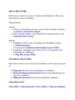
6 Mount the CCU away from sources of magnetic interference. ECU power cableYou must connect the ECU to a 12 to 24 Vdc power source. To extend this cable, use the correct wire gauge (Power Cable Extensions, page 4).CCU cableTo extend this cable to reach the ECU, you may need to use cable extensions (sold separately) (CCU Mounting and Connection Considerations, page 3).You must connect this cable to the alarm and the Shadow Drive : The Shadow Drive sensor is optional and sold separatelyDrive unitThis diagram shows only the electrical connections for the drive unit (sold separately). Detailed installation instructions are included with the drive you purchased a drive unit from Garmin , it includes the necessary power and feedback unit power and feedback cablesThe drive unit power cable cannot be cut or extended.
7 If you are using the autopilot with a drive unit not sold by Garmin , you must use a drive unit power cable (sold separately) (Connecting to an Existing Drive Unit, page 5).If you are using the autopilot with a solenoid drive unit, you must use a solenoid power cable (sold separately) (Connecting to a Solenoid Drive Unit, page 5).If you are using the autopilot with a drive unit not sold by Garmin or a solenoid drive unit, you must install a Garmin rudder feedback sensor (recommended) or connect to an existing rudder feedback sensor using a rudder feedback cable (sold separately) (Drive Unit Installation, page 5). AlarmThe alarm provides audible alerts from the autopilot system, and you should install it near the primary helm station (Installing the Alarm, page 6).
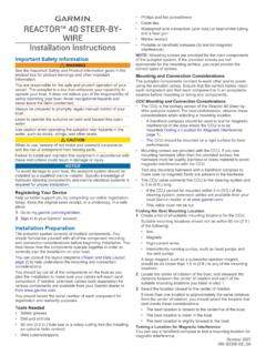
8 Shadow Drive sensor connection (optional)The Shadow Drive sensor is an optional accessory that can be used only on a boat with a hydraulic steering system (Installing the Shadow Drive Sensor, page 6).Component LayoutSingle-Helm LayoutNOTE: This diagram is for planning purposes only. If needed, specific connection diagrams are included in the detailed installation instructions for each ConsiderationsHelm controlA dedicated helm control is not included in all autopilot packages. If you install the autopilot without a dedicated helm control, the autopilot CCU must be connected to the same NMEA 2000 network as a compatible Garmin chartplotter to configure and control the autopilot to 24 Vdc batteryYou must connect the ECU to a 12 to 24 Vdc power source.
9 To extend this cable, use the correct wire gauge (Power Cable Extensions, page 4).You must connect the NMEA 2000 power cable to a 9 to 16 Vdc power can mount the CCU in a non-submerged location near the center of the boat, in any orientation (CCU Mounting and Connection Considerations, page 3).Mount the CCU away from sources of magnetic interference. Drive unitThe drive unit power cable cannot be cut or extended. If you are using the autopilot with a drive unit not sold by Garmin , you must use a drive unit power cable (sold separately) (Connecting to an Existing Drive Unit, page 5).If you are using the autopilot with a solenoid drive unit, you must use a solenoid power cable (sold separately) (Connecting to a Solenoid Drive Unit, page 5).
10 ECUNMEA 2000 networkYou must connect the helm control or compatible Garmin chartplotter and the CCU to a NMEA 2000 network using the included T-connectors (NMEA 2000 Connection Considerations, page 4).If there is not an existing NMEA 2000 network on your boat, you can build one using the supplied cables and connectors (Building a Basic NMEA 2000 Network for the Autopilot System, page 7).Mounting and Connection ConsiderationsThe autopilot components connect to each other and to power using the included cables. Ensure that the correct cables reach 2each component and that each component is in an acceptable location before mounting or wiring any Mounting and Connection Considerations The CCU is the primary sensor of the reactor 40 MECHANICAL autopilot system.