Transcription of PREVENTA™ XPS Safety Relays Emergency stop …
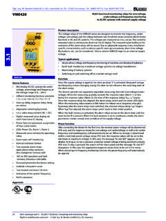
1 PREVENTA XPS Safety RelaysEmergency stop and limit switch monitoring 2003 Schneider Electric All Rights Reserved1405/03 XPSAC Safety modules for Emergency stop and limit switch monitoringOperating PrinciplePreventa XPSAC Safety Relays conform to Category 3 per EN 60954-1. They are used for monitoring : Emergency stop circuits ( Emergency stop push buttons or cable pull switches) that conform to standards EN 60418 and EN 60204-1 Limit switches or Safety interlocks mounted on guards or doors, that conform to standard EN modules have a compact enclosure ( " wide).Three Safety outputs and 1 solid state output for signaling to the versions are available: one has non-removable terminal block mounting, which is an integral part of the module, the other has removable terminal blocks to reduce maintenance time and LEDs on the cover to provide status information for easier troubleshootingSuitable for use in circuits through Category 3 per EN page 70 for InformationType of connection terminal blockNumber of instantaneous opening Safety circuitsAdditional outputsPower supply Catalog numberWeightoz (kg)Non-removable31 solid-state24 ( )48 ( )115 ( )230 ( )Removable31 solid-state24 ( )48 ( )115 ( )230 ( )
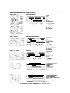
2 XPSAC ppppPFile E164353 CCN NKCRFile LR44087 Class 3211 03 efesotomasyon - telemecanique inverterPREVENTA XPS Safety RelaysEmergency stop and limit switch monitoring1505/03 2003 Schneider Electric All Rights ReservedXPSAC Safety modules for Emergency stop and limit switch monitoring Wiring DiagramsXPSAC module with an Emergency stop button with 1 contact Y1-Y2: Feedback loopESC: External start conditionsXPSAC module with an Emergency stop button with 2 contacts (recommended application) Y1-Y2: Feedback loopESC: External start conditionsFunctional diagram for module XPSAC XPSACKey to LEDs (1) Supply voltage A1-A2(2) State of K1-K2 ( Safety outputs closed)S2S1A12333Y213A2PE142434Y43Y44Y1F 1F2F3F4 K2K148 V, 115 V, 230 VK1 K2 TESCXPSAC+ 24 Vdc StartLogicS2S1K3K4K3K4K3K4K3K4A12333Y213 A2PE142434Y43Y44Y1F1 K2K148 V, 115 V 230 VK1 K2 TESCK4K3 XPSAC+ 24 Vdc StartLogic01 KeyEmergency stopactivatedEmergency stop not activatedSupplyvoltageEmergency stop A2 (02)Output 23-24 stop A1 (01)
3 Feedback loopY1-Y2 Start buttonOutput 13-14 33-34 output Y43-Y44 Not activatedActivated12 efesotomasyon - telemecanique inverterPREVENTA XPS Safety RelaysEmergency stop and limit switch monitoring 2003 Schneider Electric All Rights Reserved1605/03 XPSAV and XPSAT Safety modules for Emergency stop and switch monitoringTechnical DataModule typeXPSAV11113 and AV11113 PXPSAT ppppProduct designed for max. use in Safety related parts of control systems (conforming to EN 60954-1)Category 4 Category 4 (instantaneous Safety outputs)Category 3 (time delay Safety outputs)Power supplyvoltageV24 Vdc24 Vac/dc, 115 Vac, 230 Vacvoltage limits- 20 to + 20 % - 20 to + 10 % (24 V) / - 15 to + 15 % (115 V) / - 15 to + 10 % (230 V)frequencyHz 50/60 Power consumptionW< 5< 8 Module fuse protectionInternal, electronicInternal, electronicAdjustable time delays0 to 3000 to 30 Start button monitoringYes/No (configurable by terminal connection)Yes/No (configurable by terminal connection)Control unit voltage (at nominal supply voltage)
4 Between terminals S21-S22, S31-S32 or S11-S12 Between terminals S11-S12, S21-S22 or S11-B124 V versionVdc24 24115 V and 230 V versionsVdc 48 Calculation of wiring resistance RLbetween input terminals 100 cable length: 6,562 ft. (2000 m)RL max. = Ue = true voltage applied to terminals A1-A2U int (terminals S11-S21) = supply voltage Ue - 3 V (24 V version)U int between 42 V and 45 V, with typical value = 45 V (115 V, 230 V version)Calculated max. RL must be equal to or greater than the true valueSynchronization time between inputssFor guard: / For Emergency stop: unlimitedApprox. (automatic start, terminals S33-Y2 and Y3-Y4 linked)Outputsvoltage referenceRelay hard contactsnumber and type of instantaneous opening Safety circuits3 (03-04, 13-14, 23-24)3 (13-14, 23-24, 33-34)number and type of time delay opening Safety circuits3 (37-38, 47-48, 57-58)2 (57-58, 67-68)number and type of additional circuits3 solid state1 (41-42)breaking capacity in AC-15-- instantaneous outputsVAC300: inrush 1800, maintained 180B300: inrush 3600, maintained 360-- time delay outputsVAC300: inrush 1800, maintained 180C300.
5 Inrush 1800, maintained 180breaking capacity in DC-13-- instantaneous outputs24 A L/R = 50 ms24 A L/R = 50 ms-- time delay outputs24 A L/R = 50 ms24 A L/R = 50 msbreaking capacity of solid state outputs24 V/20 mA max. thermal current (the)-- instantaneous for all 3, or 6 for 1 and 2 for 2, or 4 for 2 and 2 for 15-- time delay for all 3, or 6 for 1 and 2 for 2, or 4 for 2 and 2 for total thermal currentA208output fuse protection conforming to IEC EN 60947-5-1. DIN VDE 0660 part 200-- instantaneous outputsA4 gG or 6 fast acting6 gG-- time delay outputs4 gG or 6 fast acting4 gGminimum current mA1010minimum voltageV1717 Electrical lifeSee page 11 Response time on instantaneous opening inputsms< 30< 20 Rated insulation voltage (Ui)V300 (degree of pollution 2 conforming to IEC EN 60947-5-1, DIN VDE 0110 parts 1 and 2)Rated impulse withstand voltage (Uimp.)
6 KV4 (over voltage category III, conforming to IEC EN 60947-5-1, DIN VDE 0110 parts 1 and 2)LED display114 Operating temperature F( C) + 14 to + 130 (- 10 to + 55)Storage temperature F( C) - 13 to + 185 (- 25 to + 85)Degree of protection conforming to IEC EN 60529 TerminalsIP 20 EnclosureIP 40 ConnectionTypeXPSAV11113 Captive screw clamp terminalsXPSAV11113 PCaptive screw clamp terminals, separate removable blockXPSAT ppppCaptive screw clamp terminals- 1-wire connectionWithout cable endSolid or stranded wire: 26-14 AWG ( - mm2)Solid or stranded wire: 24-14 AWG ( - mm2)Solid or stranded wire: 1 x 12 AWG (1 x 4 mm2)With cable endWithout bezel, stranded wire: 24-14 AWG ( - mm2)Without bezel, stranded wire:24-14 AWG ( - mm2)Stranded wire: 2 x 14 AWG (2 x mm2)With cable endWith bezel, stranded wire: 24-16 AWG ( - mm2)With bezel, stranded wire: 24-14 AWG ( - mm2) - 2-wire connectionWithout cable endSolid or stranded wire: 26-20 AWG ( - mm2)Solid wire: 24-18 AWG ( mm2)Stranded wire: 24-16 AWG ( - mm2) With cable endWithout bezel, stranded wire: 24-18 AWG ( - mm2)Without bezel, stranded wire: 24-18 AWG ( - mm2) With cable endDouble, with bezel, stranded wire:22-14 AWG ( - mm2)Double, with bezel, stranded wire: 22-14 AWG ( - mm2) U int - U min.
7 Efesotomasyon - telemecanique inverterPREVENTA XPS Safety RelaysEmergency stop and limit switch monitoring1705/03 2003 Schneider Electric All Rights ReservedXPSAV and XPSAT Safety modules for Emergency stop and switch monitoringOperating PrinciplePreventa XPSAV Safety Relays conform to Category 4 of standard EN 60954-1. Preventa XPSAT Safety Relays conform to Category 4 of standard EN 60954-1 when instantaneous break contacts are used and Category 3 of standard EN 60954-1 when time delay break contacts are are used for monitoring : Emergency stop circuits ( Emergency stop push buttons or cable pull switches) that conform to standards EN 60418 and EN 60204-1 Limit switches or Safety interlocks mounted on guards or doors that conform to standard EN vs.
8 Time Delay ContactsInstantaneous contacts (stop category 0) are used for applications where immediate removal of power is desired. These instantaneous contacts are used for most Safety delay contacts (stop category 1) allow for controlled deceleration of motor driven components until a complete stop is achieved ( : motor braking with a variable speed drive or mechanical brake). At the end of the time delay, these outputs open, removing power and drop out the XPSAV modules have: A "/45mm wide enclosure. 3 Safety outputs, 3 timed outputs, and 3 solid state outputs for signaling to the PLC. Two versions are available: one has non-removable terminal block mounting, which is an integral part of the module, the other has removable terminal blocks to reduce maintenance time and replacement.
9 Eleven LEDs on the cover to provide status information for easier troubleshootingThe XPSAT modules have: A "/90mm wide enclosure. 3 Safety outputs, 2 timed outputs, and 1 output. All the terminals are an integral part of the module (non-removable). Four LEDs on the cover to provide status information for easier troubleshootingPreventa XPSAV Safety Relays are suitable for use in circuits through Category 4 per EN 60954-1. Preventa XPSAT Safety Relays are suitable for use in circuits through Category 4 per EN 60954-1 when instantaneous break contacts are used. Preventa XPSAT Safety Relays are suitable for use in circuits through Category 3 per EN 60954-1 when time delay break contacts are page 70 for InformationType of connection terminal blockNumber of Safety circuitsAdditional outputs Power supply Catalog numberWeightoz (kg)Non-removable6 (3 time delay)3 solid state24 ( )Removable6 (3 time delay)3 solid state24 ( )Non-removable5 (2 time delay)1 ( )115 ( )230 ( )
10 File E164353 CCN NKCRFile LR44087 Class 3211 03 XPSAV11113 XPSAV11113 PXPSAT pppp efesotomasyon - telemecanique inverterPREVENTA XPS Safety RelaysEmergency stop and limit switch monitoring 2003 Schneider Electric All Rights Reserved1805/03 XPSAV and XPSAT Safety modules for Emergency stop and switch monitoringWiring DiagramsXPSAV module with an Emergency stop push button with 1 contact, automatic start or unmonitored start (1) Jumper for automatic start.(2) Instantaneous opening Safety outputs (stop category 0).(3) Time delay opening Safety outputs (stop category 1).ESC = External start diagramsAutomatic start Unmonitored startAutomatic startThere is no start contact or it is jumpered (wiring between terminals S13-S14).Note: Automatic start function is not available with 2 channel wiring on the inputs.