Transcription of Meter Relays - Crompton Instruments
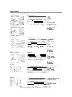
1 Web: Email: RelaysFeaturesMonitors and controls anyvariable which can beconverted to an , shock andvibration resistant designIndicator, Relays andpower unit in one housingStable electronicswitching circuit does notuse lamps, photocells,inductors or capacitorsTaut band, fluid dampedindicatorIsolated input signalLED relay state indicatorsBuilt-in 0 - 10 secondadjustable time delaysUL ApprovedFile No. E75911 SPMeter RelaysProduct CodeOne relay, two setpointsUpscale de-energized, down scale applications: Liquid level control, load shedding andpower factor relay, one set pointUpscale energized, downscale application: High Relays , two set points Mid band de-energized, outside band applications: High and Low alarm, High alarm plus shut Relays , two setpointsBoth upscale energized, downscale application: High alarm plus shutdown. 077-303 Two Relays , two setpointsHigh and low midband energized, outside band de-energized. No time application: High alarm plus Relays , two set pointsBoth upscale de-energized,downscale application: Frequency relay, one set pointUpscale de-energized, downscale application: Low Relays , two set pointsMidband de-energized, outside band from from 2, 3 or 4 wire resistance temperature detector (RTD).
2 Typical application: Temperature indication / Relays , two set pointsMidband de-energized, outside band energized. Operates from thermocouple junction compensation and thermocouple break protection are standard application: Temperature indication / 077 Meter Relays combine a highlyaccurate indicator with High and Low setpoint relay. The Relays can operate alarmand control devices when the monitoredsignal value moves outside the chosenset point limits shown by adjustable redindex single compact case houses the unitwhich requires only the input signal andpower supply thus saving space andinstallation Relays077 Series Analogue Meter RelaysApplicationsVoltage monitoring/control current monitoringOverload alarmBattery monitoring/chargingTemperature indicationTemperature controlLoad sheddingPower factor correctionFrequency monitoringLevel controlWeb: Email: RelaysMeter Relays077 Series Analogue Meter RelaysInput signal ratings:Frequency monitoring: 45/65Hz or 55/65Hz100/125 V, 200/250V380/440V or 480V Voltage:10mV to 500V - 10k Current:10 A to 500mA - 20mV drop4 Voltage:6V to 600V - 1000 Current:100 A to 1A - 1V drop5A CT operation - :Standard outputsRTD Operation.
3 10 Copper100 Platinum0-200 C, 0-150 Cor 20 - 140 x continuous, up to 200V or 100mA - 10 x for 10 Accuracy:Max error time:1 second4" Scale:100 deflectionSet point accuracy:Max error :1% of spanOperating time:250m sec to 10 sec adjustableSet-point Adjustments:Single - 100% of scaleDouble - 98% of scaleMinimum span:2% between setpointsColour:RedOutput Relay:Mounted internallyOperation:SPDT contacts on each setpointOptional latching on either orboth Relays (077-301, 077-302or 077-307 only)Contact Rating:5A, 250V, 1000W non-inductiveAmbient TemperatureRange:-10 C to +60 C (+14 F to 140 F)Standard calibration:20 C (68 F)Panel Material:Ferrous or non-ferrousDielectric test:2600V for 1 minuteAuxiliary power : Dual rating - 120/240, 50 : 12V, 24V or 125V DCBurden: 3W maximumSpecificationBRNon reflecting windowCTCalibrated at customer specifiedtemperatureEBBoth Relays latch, external switch toresetEHHigh relay latch, external switch to resetELLow relay latch, external switch to resetFKFinger knob setpoint adjustersLBBoth Relays latch, remove auxiliarysupply to resetLHHigh Relays latch, remove auxiliarysupply to resetLLLow Relays latch, remove auxiliary supplyto resetPDElectrical heavily damped movementsPGPanel mounting gasketSLRed line on instrument dialSM Customer logo on instrument dial (Note.)
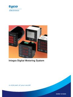
4 One off setup charge may apply)SZColoured band on instrument dialTPTPC-Time proportional control(proportional plus derivative control)OptionsConnectionsDimensions and panelcut-outLOWHIGH33 311 155 544 422 266 6 Low SetPointHigh SetPointMeter PointerAuxiliary Supply EnergisedRelay switch modes with input signalsin zone indicated by Meter pointer3 High relay1246897510 12 Input signal+ relayAuxiliarySupplyOptions110V~230V~12v 24V +-1/4-28 UNFF ixing studsTerminals10-32 UNF33/813/16331/3245/1633/833/845/16 ApprovalsE75911 SPWeb: Email: RelaysMeter Relays239 Series Analogue Meter RelaysFeaturesMonitors and controls anyvariable which can beconverted in to an signalRugged shock andvibration resistant designIndicator, Relays andpower unit in one housingControl function continuesif the indicator becomesdamagedStable electronicswitching circuit does notuse lamps, photocells,inductors or capacitorsTaut band, fluid dampedindicatorIsolated input signalLED relay state indicatorsMeter RelaysProduct CodeOne relay, two setpointsUpscale de-energised, down scale applications: Liquid level control, load shedding & power factor relay, one set pointUpscale energised, downscale application: High Relays , two set pointsMid band de-energised, outside band applications: High and Low alarm, High alarm plus shut Relays , two setpointsBoth upscale energised, downscale de-energisedTypical application.
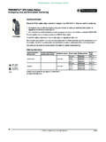
5 High alarm plus Relays , two setpointsHigh and low midband energised, outside band de-energised. No time application: High alarm plus Relays , two set pointsBoth upscale de-energised,downscale application: Frequency relay, one set pointUpscale de-energised, downscale application: Low Relays , two set pointsMidband de-energised, outside band from from 2, 3 or 4 wire resistance temperature detector (RTD).Typical application: Temperature indication / Relays , two set pointsMidband de-energised, outside band energised. Operates from thermocouple input. Cold junction compensation and thermocouple break protection are standard application: Temperature indication / 239 Meter Relays combine a highlyaccurate indicator with High and Low setpoint Relays . The Relays can operatealarm and control devices when themonitored signal value moves outside thechosen set point limits shown byadjustable red index single compact case houses the unitwhich requires only the input signal andpower supply thus saving space andinstallation monitoring/control current monitoringOverload alarmBattery monitoring/chargingTemperature indicationTemperature controlLoad sheddingPower factor correctionFrequency monitoringLevel controlWeb: Email: RelaysMeter Relays239 Series Analogue Meter RelaysAdjustmentsFront panel comprises Set-point potentiometer(s),one per set-pointRear panel comprises Delay potentiometer(s), oneper set-pointMeasuring Input:Note:All inputs are average sensing, but Voltage:10V to 600V RMS (Sensitivity 1K /V to100K /V,max.)
6 Current:1mA to 15A RMS (20mVdrop) Voltage:10mV to 600V RMS (Sensitivity 1K /V to100K /V,max. Centre zerooption up to 600/0 Current:100 A to 15A (20mV drop) Centre zero option up to15/0/15 ampsMaximum continuousinput x rating continuously(600V max.)Maximum continuousinput x nominal (15A max.)Maximum short durationinput current6 x nominal for 6 seconds(30A max.)Frequency monitoring: 50Hz to 60Hz 10%Burden< time:1 second4 Scale:100 deflectionPanel material:Ferrous or non-ferrousDielectric test:2600V for 1 minuteAuxiliary supplyAux. voltage , 120, 220, 230, 240,277, 480V ( 20%)Aux. voltage , 24, 48, 120, or 135 Vmaximum 156V frequency50 to 60Hz 10%Burden: < and AccuracyIndicator accuracyClass range98% of scaleSet-point accuracy1% of rangeSet-point hysteresis 1% of rangeTrip of rangeRelay tripping time<1 secondTime delay0 to 20 seconds, adjustableby potentiometer on rearpanelOption:0 to 10seconds and 0 to 40 secondsIndicationSingle red LED, per set-point,to indicate trip conditionOutputsRelaysDPCO contactsrated 5A @ 250V 5A @ 30V resistiveelectrical life >104operations@ 5A, 250V class IIB (IEC 60255-0-20)Relay logicConfigurable to energise orde-energise on tripOptionsRelay latchingWhen the measured signalreaches the set-point, therelay changes state andstays in this condition untilthe auxiliary supply isinterruptedEnvironmental and MechanicalAmbient temperaturereference range+15 C to +30 Cnominal range of use0 C to +60 CStorage temperature -20 C to +70 CRelative humidity<90%, non condensingShock15g/11ms (EN 60068-2-27)Bumping40g/6ms (EN 60068-2-29)Vibration10 to 300Hz (EN 60068-2-6)Protection class(BS EN 60529))
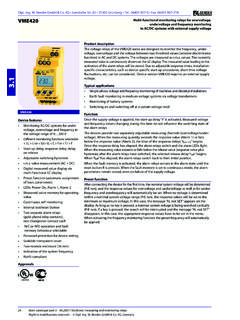
7 Terminals to IP20 Enclosure to IP50 EnclosureFlammabilityUL94V1 Terminal capacities1 to 4mm2solid or strandedconductorsWeight<1kgEU DirectivesLow Voltage Directive 73/23/EEC amended by93/68/EECEMC Directive89/336/EEC amended by93/68/EECCE Mark Directive93/68/EECS pecificationCTCalibrated at CEBBoth Relays latch, external switch toresetEHHigh relay latch, external switch toresetELLow relay latch, external switch toresetFKFinger knob setpoint adjustersKVSensitivity 100k/volt for inputKW Sensitivity 1k/volt for inputK X Sensitivity 100k/volt for inputLBBoth Relays latch, remove auxiliarysupply to resetLHHigh Relays latch, remove auxiliarysupply to resetLLLow Relays latch, remove auxiliarysupply to resetMC Clamp band fixingNH HysteresisPD Electrical heavily damped movementsPG Panel mounting gasketRP Retro-fit plate 237 Meter relaySLRed line on instrument dialSM Customer logo on instrument dial (Note:one off setup charge may apply)S ZColoured band on instrument dialTPTPC-Time proportional control(proportional plus derivative control)OptionsWeb: Email: RelaysMeter Relays239 Series Analogue Meter RelaysDimensions and Panel cut-outConnectionsMeasuring InputTerminal1 Meter N or -VE2 Meter L or +VE3, 4.
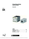
8 RTD or Thermocouple supply neutral (-ve if ) supply live (+ve if ) supply tap for dual "( ) "( ) "( ) "( )A = 4" ( )B = 2" ( )c = " ( ) "(116mm) "( ) "(115mm) "(12mm)4 STUDS 4-40 " lg (14mm)ZEROADJUSTERHIGH SET POINTADJUSTERLOW SET POINTADJUSTERWeb: Email: RelaysMeter Relays244 Series Analogue Meter RelaysMeter RelaysProduct Code1 relay, 2 set-pointsUpscale de-energised, downscale energised244-3001 relay, 1 set-pointUpscale de-energised, downscale energised244-3012 Relays , 2 set-pointsMid-band de-energised, outside band energised244-3022 Relays , 2 set-pointsBoth upscale energised, downscale de-energised244-3032 Relays , 2 set-pointsHigh & low mid-band energised, outside band de-energised244-3042 Relays , 2 set-pointsBoth upscale de-energised, downscale energised244-3051 relay, 1 set-pointUpscale de-energised, downscale energised244-3072 Relays , 2 set-pointsHigh and high upscale de-energised244-3081 relay, 2 set-pointsLow de-energised, high energised244-309 RDT operated 2 Relays , 2 set-pointsMid-band de-energised, outside band energised244-30 RThermo couple 2 Relays , 2 set-pointsMid-band de-energised.
9 Outside band energised244-30T244 series Meter Relays combine a highlyaccurate indicator with high and low set-pointswhich can operate alarm and control circuitswhen the monitored signal value moves outsidethe set-point limits indicated by the adjustablered index Relays monitor and control any parameterwhich can be converted into an or indicator, Relays and power unit are in onehousing and the control function continuesshould the indicator become damaged. A timedelay is available as an optional windowCTCalibrated at customer specifiedtemperatureDSDual scaleFKFinger knob adjustmentLBBoth Relays latch, remove auxiliarysupply to resetLHHigh Relays latch, remove auxiliarysupply to resetLLLow Relays latch, remove auxiliary supplyto resetPDHeavily damped movementPGPanel gasketSLRed line on dialSM Customer logo on dialSNNo logo on dialSRRed index line on dialSZColoured band on dialTBTime delay - 10 secTCTime delay - 30 secTDTime delay - 20 secTHTime delay - 10 sec high relayTITime delay - 30 sec high relayTLTime delay - 10 sec low relayTM Time delay - 30 sec low relayTPTime proportional controlOptionsApplicationsVoltage monitoring/control current monitoringOverload alarmBattery monitoring/chargingTemperature indicationTemperature controlLoad sheddingPower factor correctionFrequency monitoringLevel controlApprovalsE75911 SPWeb: Email.
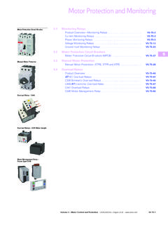
10 RelaysMeter Relays244 Series Analogue Meter RelaysAccuracy Indicator:Class :Class :1% of spanSet-point adjustment:98% of scaleMinimum span:2% between set Volts:6V to 500V (1K /V)50/60Hz Single Frequencies:25Hz to 3kHz on Current: 100 A to 1A (1V drop) 1A &5A operation ( )50/60Hz. Frequencies:25Hz to 3kHz on requestTime to 10 or to 30secondsOptional Volts:20mV to 500V (10K /V) Current:10 A to 15A (20mV drop)Thermocouple:Types J, K, R, S, T minimum10mV spanRTD:2 wire 10 copper 100 platinum, 120 nickelAuxiliary :Dual rating 100/125V or200/250V 50 :12V or 24V. +/-14% Maximum 15% ripple onunregulated supplies Burden:3VA maximumFixing:Screw clampsEnclosure:IP52 SpecificationDimensionsConnections107969 29296 Panel cut-outMaximum panelthickness CURRENTINPUT ABOVE100mA 8mm2M4 TERMINALSN/O N/C COM COM N/C N/OLOWHIGHSETPOINTSETPOINTHIGH SETPOINTTIMEDELAYINPUTAUXILIARYLL+-N110V 230 VLOW SETPOINTTIMEDELAY