Transcription of Paladin and Integra Transducers - Crompton …
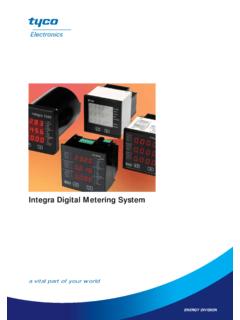
1 Crompton Instruments Integra and Paladin TransducersFeaturesExtensive rangeHigh accuracyTrue RMS measurementTHD measurement and power quality dataPulsed, analogue and digital outputsBenefitsCost saving remote meteringDIN-rail or base mounted optionsEfficient monitoring, control and protection of expensive power assetsApplicationsSwitchgearDistribution systemsGenerator setsControl panelsEnergy managementBuilding managementUtility power monitoringProcess controlMotor controlApprovalsUL, CSA and BVContents PageIntegra 1560 and 1580 Digital transducer Systems2 6 Paladin Transducers AT Series Class 11 Paladin Transducers 250 Series Class and 24 Paladin Transducers 250 Series Dimensions25 Paladin Transducers 250 Series Connection Diagrams26 29 Integra and Paladin TransducersAn extensive range of Transducers providing measurement, isolation and conversion of electricalparameters into industry standard DC output signals. The range offers protection against highvoltage and overload, and resistance to vibration in harsh electrical transducer range also offers multiple analogue outputs in a single housing and individualmeasurement of most electrical Digital transducer SystemsIntegra 1560 and 1580 Transducers provide high accuracy < and communicate up to 50 major electrical and powerquality parameters, including true RMS system values, power quality dataand total harmonic distortion (THD) measurement up to the 31st range includes the rail mounted 1560 DIN version and the 1580 variantwith a base plate for surface mounting.
2 OperationThe multi function Integra 1560 and 1580 Transducers offer uncomplicatedoperation and high accuracy < measurement of single and three-phase voltage,current, frequency, Watts, VAr, VA, energy and power factor, and total harmonicdistortion measurement of both phase and system current and voltage. A simpleWindows based software package is provided to configure the transducer . Onceconfigured, up to 50 electrical and power quality variables can be simultaneouslyinput into building management systems via pulsed, analogue and digitalcommunication options. Status may also be monitored via a PC through a software , an optional menu driven display unit can be used to configure andmonitor up to 32 measured parameters. Display panel unit can be permanentlymounted next to the transducer or simply connected at times when configuration,adjustment and/or status information is Transducers utilise true RMS measurement techniques up to the 31stharmonic, providing < accuracy. An exceptional tolerance to high harmonicfrequencies is achieved from the robust frequency detection method, which is ableto lock the fundamental frequency onto any phase.
3 High integrity measurementsare possible where the system approximates CT current in the absence of voltage InputDesigned for all low, medium and high voltage switchgear and distributionsystems, the Transducers offer programmable VT and CT ratio capability. Directconnection up to 480V AC with 5A CT inputs is standard, and 1A CT inputs are OutputsPulsed outputsOptional pulsed outputs enable retransmission of kWh and kVArh time basedparameters. Outputs are pulsed at a rate proportional to the measured kWh activeenergy, with programmable pulse width and rate. Output relays have fully insulatedvolt free contacts, with connection via screw clamp outputsUp to four analogue outputs may be included, enabling transmission of linearparameters. Each analogue channel can be assigned to one of 47 measuredparameters with fully adjustable output span and can be configured to operate innormal, reverse, threshold or constant current modes. Analogue outputs share acommon return which is galvanically isolated from non-analogue output Digital CommunicationsRS485 Modbus RTUI ntegra 1560 and 1580 Transducers have two RS485 communication ports fordirect connection to SCADA systems with Modbus RTU protocol, oroptionally a single Johnson Controls Metasys NII protocol.
4 The Modbus optionincludes function 8 subfunction 0, which provides return query data diagnosticsupport and the ability to change Modbus word order to suit user OptionThe Lonworks option conforms to LonMark Interoperability Guidelines version can be integrated into a single control network without requiring acustom node or network tool development. Lonworks implementations include aModbus port. This Modbus port is used when a local Integra display is required orfor setting up the unit from Crompton Instruments configuration Measure and communicate up to 50 electrical and power parameters High accuracy of < THD measurement and power quality data True RMS measurement Pulsed, analogue and digital outputs Modbus and Lonworks interfaceoptions Fully programmable VT and CT ratios Configurable via software or menudriven interface Benefits Replaces multiple single functiontransducers DIN-rail or base mounted options Local or remote configuration andmonitoring via building managementsystems ANSI style local or remote LED display option Monitoring, control and protection of expensive power assetsApplications Switchgear Distribution systems Control panels Energy management Building management Utility power monitoring Process control Motor monitoringApprovals UL file no.
5 E200300 CSA pending2 Profibus OptionThe Profibus option provides an RS485 interface capable of operating at up to10Mb/s. Profibus implementations include a Modbus port. This Modbus port is usedwhen a local Integra display is required or for setting up the unit from Cromptonconfiguration ConfigurationConfiguration of up to 50 measured parameters, outputs, pulsed relays, currentand power demands are programmed through a Windows style user transducer is connected to a PC s COM port via an RS485/RS232 converter. The software allows the user to load and save configuration settings to and from aPC hard disk, and to send and retrieve settings from the transducer . Settings canbe saved for later use and can be copied from one Integra transducer to another. Status information is usually communicated into a building management system,but can also be monitored through configuration software. The softwareinterrogates the selected transducer every few seconds to obtain data, which canbe viewed on a dedicated measurements Display Unit OptionAs an alternative to the standard software configuration package, voltage and currenttransformer ratios, communication options and power measurement parameters canbe configured via the optional menu driven Integra DIS-1540 display unit.
6 A simple two button interface on the front panel of the unit allows display of 32 majorelectrical and power quality parameters. All set-up screens are password configured, the status of each parameter can be viewed by scrolling through 13 screens, featuring a 3 line, 4 digit LED display. The unit requires an independentauxiliary power supply and thus may be positioned either locally, or remotely from the transducer at a distance limited only by the communication restrictions of ParametersIntegra 1560 and 1580 Transducers are programmed via the RS485communications port using the configuration software for a Windows based PC, or by using the optional programmable Integra DIS-1540 display unit. 3 Measurement and communicationUp to 50 electrical and power qualityparameters can be L1-N, L2-N, L3-NVolts L1-L2, L2-L3, L3-L1 System volts L-N (average)System volts L-L (average)Current line 1, 2 and 3 System current (average)Current sumCurrent demandCurrent maximum demandNeutral currentSystem frequencyWatts 1, 2 and 3 System Watts (sum)Watts demand (import)Watts maximum demand (import)Watt-hours (import)VAr 1, 2 and 3 System VAr (sum)VAr-hours (import)VA 1, 2 and 3 System VA (sum)Power factor 1, 2 and 3 System power factor (average)Phase angle 1, 2 and 3 System phase angle (average)THD volts 1, 2 and 3 THD system volts (mean)THD amps 1, 2 and 3 THD system amps (mean)Measurement and display Up to 32 electrical and power qualitymeasurements can be configured andmonitored on the DIS-1540 optionaldisplay unit.
7 These parameters appearin the following System voltsSystem currentSystem kW2 System volts THD %System current THD %3 Volts L1 N (4-wire only)Volts L2 N (4-wire only)Volts L3 N (4-wire only)4 Volts L1 L2 Volts L2 L3 Volts L3 L15 Volts Line 1 THD %Volts Line 2 THD %Volts Line 3 THD %6 Current L1 Current L2 Current L3 7 Current Line 1 THD %Current Line 2 THD %Current Line 3 THD %8 Neutral current (4-wire only)FrequencyPower factor9 kVArkVAkW10 kW Hr (7 digit resolution)11 kVAr Hr (7 digit resolution)12 kW demandCurrent demand13 kW maximum demandCurrent maximum demandParameterRangePassword:4 digit, 0000 - 9999 Primary current:max 9999A (360MW max**)VT primary:400kV (360MW max**)Secondary voltage:nominal system voltage** maximum VT and CT ratios are limited so thecombination of primary voltage and current doesnot exceed 360MW at 120% of relevant inputDemand integration time: 8, 15, 20, 30 minutesReset:max demand and active energy registersPulse output duration:60, 100, 200 msPulse rate divisors:1, 10, 100, 1000RS485 interface baud rate: , , , parity:odd/even/no, 1 or 2 stop bitsModbus address:1 - 247 Analogue outputs:user definable parameters and ranges4 Input Nominal input 277V L-N, 100 480V L-LMax continuous input voltage: 120% of nominalMax short duration input voltage: 2 x for 1 second, repeated 10 times at 10 second intervalsSystem VT ratios (primary):any value up to 400kV **Nominal input voltage burden: < VANominal input current:5A (1A option)System CT primary values:9999 max 360MW **Max continuous input current:120% nominalMax short duration current input: 20 x for 1 second, repeated 5 times at 5 second intervalsNominal input current burden: < VA** maximum VT and CT ratios are limited so the combination of primary voltageand current does not exceed 360MW at 120% of relevant inputOutputsRS485 communications:two-wire half duplex Baud rates.
8 2400, 4800, 9600, 19200 Pulsed: clean contact SPNO, 100V DC maxPulse duration:60, 100 or 200 millisecondsPulsed outputs:up to 2 Analogue outputs:up to 4 AuxiliaryStandard nominal supply voltage: 100 250V, AC or DC (85 287V, AC absolute)(85 312V, DC absolute)AC supply frequency range:45 66 HzAC supply burden:6 VA Optional auxiliary DC supply:12 48V, DC( 60V, DC absolute)DC supply burden:6 VA Measuring rangesVoltage:80 120% of nominal (functional 5 120%)Current:5 120% of nominal (functional 5 120%)Frequency:45 66 HzPower capacitive 1 inductiveTHD:Up to 31st harmonic 0% 40%Energy:7 digit resolution Reference conditionsAmbient temperature:23 1 CInput frequency:50 or 60Hz 2%Input waveform:sinusoidal (distortion factor < )Auxiliary supply voltage:nominal 1%Auxiliary supply frequency:nominal 1%AC auxiliary supply waveform: sinusoidal (distortion factor < )Magnetic field of origin:terrestrial fluxAccuracy Voltage: of range Current: of range of mid frequencyPower: of range Power factor:1% of unityReactive power (VAr): of rangeApparent power (VA): of rangeTHD: 1% Neutral current: of rangeEnergy:KWh 1% IEC1036 KVArh:2% Temperature coefficient:voltage and current typical: C Watts typical: CUpdate time:1 second for display, 250 ms for optional digital portAnalogue output: DefinitionError changes due to quantity variations as described in IEC688:1992 section accuracy based on a typical harmonic continuedEnclosureEnclosure style:DIN-rail or base mountedCompliant with:UL E200300 and IEC 1010/BSEN 61010-1 Material:Polycarbonate with additional metal base plate on the 1580 for surface mountingTerminals:Shrouded screw clamp with additional metal base plate on the 1580 for surfacemountingDielectric voltage:Tested at RMS 50Hz for 1 minute between all electrical circuitsOperating temperature:-20 to +60 CStorage temperature:-30 to +80 CRelative humidity:0 90% non condensingWarm-up time.
9 1 minuteShock:30g in 3 planesVibration:10 55Hz, amplitudeDIN-rail transducer dimensions: " high* x " wide x " high x wide x deep *Excluding connectorsBase mounted transducer " high* x " wide x " high x 95mm wide x deep *Excluding connectorsTransducer display dimensions: " high x " wide x " high x wide x deepPanel cut out (display): " (103mm) diameter, 4 stud positionsOrdering CodesINT-1561-*-5-**-option-** Integra 1560 1-phase 5A CT input, DIN-railINT-1562-*-5-**-option-** Integra 1560 1-phase 3-wire 5A CT input, DIN-railINT-1563-*-5-**-option-** Integra 1560 3-phase 3-wire 5A CT input, DIN-railINT-1564-*-5-**-option-** Integra 1560 3-phase 4-wire 5A CT input, DIN-railINT-1581-*-5-**-option-** Integra 1580 1-phase 5A CT input, base mountINT-1582-*-5-**-option-** Integra 1580 1-phase 3-wire 5A CT input, base mountINT-1583-*-5-**-option-** Integra 1580 3-phase 3-wire 5A CT input, base mountINT-1584-*-5-**-option-** Integra 1580 3-phase 4-wire 5A CT input, base mount*Input voltage 139V L-N1561 and 1581114 278V L-L ( 139V L-N) 1562 and 1582100 240V L-L ( 139V L-N) 1563,4 and 1583,4M140 277V L-N1561 and 1581279 480V L-L (140 240V L-N) 1562 and 1582241 480V L-L (140 277V L-N) 1563,4 and 1583,4**Auxiliary supply suffixL12 48V DCM100 250V AC/DC** Communications suffixDescriptionCat.
10 112111 1112211 1212311 1312411 142102122021 1 Pulsed/relayoutputsRS485 ModbusRS485 interfaceModbus orJohnson ControlsMetasys NIIP rofibusLonworksAnalogueoutputsSample order codeINT-1564-M-5-M-120 Integra 1560 transducer , 3-phase 4-wire, DIN-rail mounted, 241 to 480V L-L nominal input voltage, 5 A CTinput, auxiliary supply 100 250V AC or DC, one relay pulsed output and two RS485 Modbuscommunication code for analogue outputs=1 0-20 mA, 10V compliance (userconfigurable as 4-20 mA)=3 -1/0/+1 mA, 10V compliance6 DimensionsIntegra 1560 DIN-rail Mounted TransducerOptional Remote Display (for use with Integra 1560 or1580 transducer )Optional Remote Display Panel Cut-Out1560/1580 - 3-phase 3-wire Unbalanced LoadAuxiliary SupplyThe Integra family should ideally be powered from a dedicated supply, either 100 250V AC or DC (85V 280 AC absolute or 85 312V DC absolute) or 12-48V DC( 60V DC absolute). However, all Integra devices may be powered from asignal source, if in the working range of the chosen auxiliary is recommended that all voltage lines be fitted with 1 amp ConnectionsFor safety reasons, all CT secondary connections should be grounded inaccordance with local regulations.