Transcription of Primary and Secondary Electrical Distribution Systems
1 Primary and Secondary Electrical Distribution Systems Critical Facilities Round Table 12th Quarterly Membership Meeting June 2, 2006. David D. Roybal. Eaton Electrical Cutler-Hammer Products Utility Considerations Capacity Voltage and Sources Size of Metering Equipment Relaying Requirements Station Batteries Utility Metering Requirements Dictated by the Utility EUSERC (as a reference). 15 kV: 48 W x 72 to 96 D. 21 kV: 60 W x 96 D. 38 kV: 72 W x 129 D. 115 kV Substation Service (Approximately 80' by 75'). Types of Systems Radial Primary -Selective Radial Loop- Primary Selective Secondary Selective Sparing Transformer Spot Network Simple Radial System Simple, least costly Easy to coordinate No idle parts Radial System Primary and Secondary Radial Loop Primary Radial Secondary Loop Switching Substation Transformer Loop Switching Pad Mount Transformer Primary Selective Radial System Duplex or selector switch Spare Primary incoming circuit Duration of outage from cable failure limited Primary Selective.
2 Secondary Radial Duplex Selector Switch Selector Switch Single Structure Secondary Selective System Normally operated as two electrically independent substations with tie breaker open Failure of either Primary circuit affects only one bus Service restored by opening dead bus main and closing tie Operation can be made automatic Transformers not paralleled so fault currents similar to radial Two-Source Primary . Secondary Selective Sparing Transformer System Alternative to Double-Ended Substations Single Common Backup Transformer Service restored by opening dead bus main and closing tie Operation can be made automatic Transformers not paralleled so fault currents similar to radial Location of substations limited (must be clustered). Sparing Transformer Spot Network Transformers paralleled on the Secondary side Uses network protectors If Primary voltage fails, associated protector automatically opens Other protector remains closed No dead time on bus, even momentarily Upon voltage restoration automatically synchronizes and re-closes Improved voltage regulation Secondary fault current increased Spot Network Primary Equipment Air Terminal Chamber Metal-Clad Switchgear Circuit Breaker and Relays Metal-Enclosed Switchgear Switch and Fuse Others (Reclosers and Interrupters).
3 Metal-Clad Switchgear Defined in ANSI as metal enclosed power switchgear Removable (draw-out) type switching and interrupting devices Connect and disconnect position Major parts of the switchgear enclosed by grounded metal barriers for compartmentalization Automatic shutters that cover Primary stabs or studs All Primary bus conductors and connections covered with insulation material throughout Protective Relays (ANSI Device Numbers). 27 - Undervoltage 47 - Phase sequence 49 - Thermal overload 50 - Instantaneous 51 - Time overcurrent 59 - Overvoltage 63 - Sudden pressure 67 - Directional overcurrent 86 - Lockout 87 - Differential Metal-Enclosed Interrupter Switchgear Defined in ANSI as metal-enclosed power switchgear Interrupter switches Power fuses (current limiting or non-current limiting). Bare bus and connections Instrument transformers Control wiring and accessory devices Power Fuse Coordination Expulsion Inverse-time Easier to coordinate Current Limiting Steep straight line More difficult to coordinate Pad Mounted Transformer Switching and Fusing LBOR Switch Oil Interruption Rated 200, 300, 400 A.
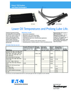
4 Isc = 12 kA. Current Limiting and Expulsion Fuses Limited Sizes Transformers Unit Substation Transformers through 20,000 kVA. Maximum 69 kV Primary Maximum kV. Secondary Bushings wall mounted Part of a substation lineup Can be custom designed to meet custom dimensions Padmount Transformers Up to 5,000 kVA. Maximum kV Primary Maximum 600 V Secondary Weather resistant high and low voltage compartments Tamper-resistant Design No Fan Cooling Available 6. Network Transformers 300-2500 kVA. Maximum kV Primary Maximum 600 V Secondary Used in areas of high load density Designed for use in a Secondary network system in either subway or vault applications. Dry Versus Liquid Transformers Dry Liquid No fluid to spill or burn Lowest purchase price Cost is higher than oil Hermetically sealed tank for harsh environments Resistant to moisture and Lowest losses per chemical contamination purchase dollar Minimum maintenance Best balance of design UL Listing is available properties- dielectric, thermal, and cost UL Listing is available Liquid Filled Technology Benefits Lowest Purchase Cost Lowest Loss Per Purchase Dollar Ability to operate in adverse conditions Excellent Dielectric Properties Smaller Footprint Better losses Options available for Safety- Related and Environmentally Sensitive Applications.
5 Dry Type Technology Benefits Environmentally Safe Non-flammable Minimal Maintenance Coordination Flexibility Higher Fan Cooled Rating Comparison of Transformer Costs Liquid Filled Transformers Mineral Oil (Outdoor) Vegetable Oil (Indoor/Outdoor) Silicone (Indoor/Outdoor) Pad Mounted 5% Less than Substation Design Dry Type Transformers Vacuum Pressure Impregnated Vacuum Pressure Imp. - Epoxy Cast Coil to Lower Temperature Rise 15% to 35%. Outdoor Add 20%. Loss Evaluation I2R Losses = Total Losses (TL) - No Load Losses (NL). I2R Losses are proportional to the Load Factor Squared Load Factor = Actual Load kVA/Rated Base kVA. Operating Losses = No Load Losses + I2R Losses at the appropriate Load Factor Loss Evaluation Example Losses in watts for a 1000 kVA oil-filled transformer: 1,800 watts no load losses 15,100 watts full load losses Load losses are approximately 13,300 watts (15,100 1,800). At 0% load: 1,800 watts At 50% load: 1,800 watts + (13,300)(.5)2 = 1,800 watts + 3,325.
6 Watts = 5,125 watts At 100% load: 1,800 watts + 13,300 watts = 15,100 watts At 110% load: 1,800 watts + (13,300)( )2 = 1,800 watts + 16,093. watts = 17,893 watts Auxiliary Fan Cooling Liquid filled transformers Fan cooling - 15% (750 kVA to 2000 kVA). Fan cooling - 25% (2500 kVA and above). Dry type transformers Fan cooling - 33% (All ratings). Environment Maximum altitude 1000 m (3300 feet). Rating reduced to for each 100 m (330 feet) above that altitude Indoor and outdoor designs available Ambient 30 degree C (86 degree F) average over 24 hours 40 degree C (104 degree F) maximum Transformers - Liquid Filled Insulation Systems (Oil, Silicone, Vegetable Oil). Temperature rise 55 degree C. 65 degree C. Efficiency - 99%. Overload capacity - ANSI Auxiliary devices Temperature gauge Liquid level gauge Pressure vacuum gauge Sudden pressure relay Pressure relief device Transformers - Dry type Insulation Systems Varnish Polyester Silicone Epoxy Design types Dip and bake VPI. Cast coil Insulation classes Class H 220 degree C.
7 Class F 185 degree C. Class B 150 degree C. Transformers - Dry Type Temperature rise 150 degree C. 115 degree C. 100 degree C (epoxy). 80 degree C. Efficiency 97% to 98% (typical). 99% (low temperature rise). Overload capacity - ANSI Auxiliary devices Temperature gauge Secondary Neutral Grounding Solid Grounding Impedance Grounding Low resistance High resistance Reactance Secondary Equipment Air terminal chamber Busway Low voltage switchboard Molded Case Circuit breakers Metal-Enclosed Switchgear Low voltage Power circuit breakers Low-Voltage Switchboards (UL891). Versus Metal-Enclosed Switchgear (UL1558). Paralleling Switchgear Low-Voltage Switchboards (UL891). Versus Metal-Enclosed Switchgear (UL1558). Molded Case Circuit Breakers (UL489). Insulated Case Circuit Breakers (UL489). Power Circuit Breakers (UL1066). Front Access or Rear Access Drawout or Fixed Mounted Manually or Electrically Operated Low-Voltage Circuit Breaker Types Molded Case Circuit Breakers Tested in accordance with UL489 & Nema AB-1.
8 Open Air Test - Rated @ 80% (Optional 100%). Over Toggle Mechanism Sealed Case - Not Maintainable Applied in Switchboards/Panelboards Insulated Case Circuit Breakers Tested in accordance with UL489 & Nema AB-1. Open Air Test - Rated @ 80% or 100%. 2-Step Stored Energy Mechanism Sealed Case - Not Fully Maintainable Applied in Switchboards Power Circuit Breakers Tested in accordance with UL1066 & ANSI C37. Tested in the Enclosure - Rated @ 100%. 2-Step Stored Energy Mechanism Open Access - Fully Maintainable Applied in Metal-Enclosed Draw-out Swgr Low-Voltage Circuit Breaker Typical Ratings Molded Case Circuit Breakers Frame Size: 100 through 3000 ampere Interrupting: 10/35/65/100 kA @ 480 Volts Limiters Available: 200 kAIC. Instantaneous: 10-13X Frame Rating @ various X/R. Insulated Case Circuit Breakers Frame Size: 400 (800) through 5000 ampere Interrupting: 65/85/100 kA @ 480 Volts Limiters Not Normally Available Time: 25/35/65 kA @ various X/R. Power Circuit Breakers Frame Size: 800 through 5000 ampere Interrupting: 65/85/100 kA @ 600 Volts Limiters Available: 200 kAIC.
9 Short Time: 35/65/85/100 kA @ X/R of TCC with Power Circuit Breakers PCB 2400 amp 480V, Microprocessor Trip, LS. Frame size: 3200 A. Sensor: 2400. PCB- LTPU: f(S) = 2400 amp STPU: f(s) = 12000 amp 2400A LTD: sec. STD: .3 sec. No Instantaneous Trip PCB- 800A PCB 800 amp 480V , Microprocessor Trip, LS. Frame size: 800 A. Sensor: 800. MCCB- LTPU: f(S) = 800 amp 200A STPU: f(s) = 4000 amp LTD: sec. STD: .1 sec. No Instantaneous Trip MCCB- 50A MCCB 200 amp 480V, Microprocessor Trip, LSI. Frame size: 250 A. Trip: 200 A. Inst. PU: *T = 2000 A. MCCB 50 amp 480V, Thermal-Magnetic Trip Frame size: 100 A. Trip: 50 A. Inst. PU: Non adjustable Maintenance - MCCBs and ICCBs Enclosed design requires little maintenance Terminal connections and trip units tightened to the proper torque values Inspect conductors Visually inspect and operate periodically Replacement parts are not available Repair, refurbishment, or remanufacture not recommended - replace damaged breakers Maintenance - PCBs Designed to be serviced Replacement parts are available (contacts, pole assemblies, arc chutes).
10 Inspection and maintenance program is recommended Keep it dry, keep it clean, keep it tight Primary and Secondary Electrical Distribution Systems Critical Facilities Round Table 12th Quarterly Membership Meeting June 2, 2006. David D. Roybal. Eaton Electrical Cutler-Hammer Products