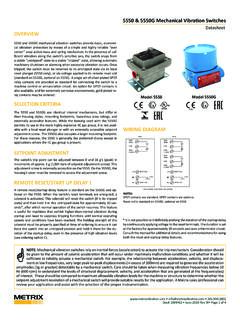
Transcription of PRO Vibration Switch Family Datasheet
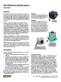
1 # 1028084 Rev R July 2017 Page 1 of 14 OVERVIEWThe PRO Vibration Switch Family consists of the PRO440, the PRO450, and the PRO6000. These switches have nearly identi-cal* functionality and differ only by the enclosure mounting style and rating, allowing placement on or near the machine in the environmental conditions and hazardous area classifications typical of industrial plants. Each Switch in the PRO Family is programmable via a USB port and PRO configuration software, or via the Switch s integral keypad/display. Advanced capabilities allow PRO switches to de-liver self-contained, single-channel Vibration protection with one or (optional) two fully adjustable alarm levels and corresponding electro-mechanical relays. Alarm and startup delays are inde-pendently programmable, local reset capabilities are provided, and terminals are available for remotely invoking Switch bypass and Switch reset. Independent 4-20 mA and buffered transduc-er output wiring terminals are provided for connection to plant control systems and condition monitoring instruments.
2 Status LEDs and a 2-line alphanumeric display are standard, allowing the user to locally assess Vibration levels, alarm conditions, and sensor OK conditions. * The PRO450 is available with an optional internal BNC connec-tor for the buffered signal output. This option is not available on the PRO440 or PRO6000. This housing is not available with a viewing window and the cov-er must be removed to use the display. It is intended primarily for applications where an 450 is being upgraded. Replacement of the housing rather than just the internals ensures that the housing s nameplate will carry the PRO Switch s serial number, part number, and other details, rather than those of the 450 it is replacing. When both a viewing window and Div 1 or Zone 1 hazardous area approvals are required, the PRO6000 should be used instead. It is smaller than the PRO450 in every dimension and uses a stud mount. An optional adapter is available for flat-base mounting (p/n 7084-001); however, it uses a different hole pattern than the 450 and will require new holes to be drilled in the mounting basic Switch /sensor configurations are supported by all 3 housing styles:1.
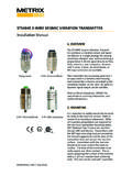
3 Internal SensorWhen ordered with an internal accelerometer, the Switch can be mounted directly at the measurement location and can monitor Vibration in either acceleration units or integrated acceleration (velocity) units. This configuration is suitable when there is suf-ficient room at the measurement location to mount the Switch , when the measurement location still allows the Switch to be conveniently viewed and serviced by plant personnel, and when the Switch s inertial mass will not compromise the quality of the Vibration measurement. PRO Vibration Switch FamilyDatasheet PRO440 This housing uses the same 3-hole flat-base footprint as the older 440 Switch . It is 22mm taller and 41mm wider than its predecessor and has two conduit fittings instead of one. The cast aluminum housing carries a NEMA 4/4X/IP65 rating and comes standard with a viewing window and powder-coat epoxy. PRO6000 This Explosion-Proof (XP) cast alumi-num housing is nearly identical in all dimensional aspects to those of its predecessor, the SW6000/SM6100.
4 The housing carries a NEMA 4/4X/IP65 rating and comes standard with a viewing window and powder-coat epoxy. It uses a stud mount. An op-tional adapter is available for flat-base mounting (p/n 7084-001). PRO450 This Explosion-Proof (XP) cast alumi-num housing is the same as used with the older 450. It carries a NEMA 4 rating and comes standard with a gray painted finish. 2. External SensorThe PRO supports connection of an external Vibration sensor (constant-current accelerometers, piezo-velocity sensors, and moving-coil velocity sensors). When possible, an external sensor is generally preferred for most applications. This configuration allows the sensor to be mounted at the ideal measurement location and orientation on the machine, without concern for the larger mounting footprint of the PRO compared to a sen-sor. It also allows the PRO to be mounted in a more convenient location for viewing and servicing. Also, although the PRO is packaged to survive harsh environments of dust, moisture, and corrosion, some machines may exhibit elevated temperatures at the preferred sensor location.
5 Use of an external sensor can allow a sensor with an elevated temperature rating, beyond that of the PRO Switch electronics. The PRO Switch also accepts generic transmitter signals such as from Vibration *, impact, temperature, level, flow, and others that provide an ISA-standard proportional 4-20 mA output. However, the PRO is not directly compatible with temperature sensors such as RTDs and thermocouples; an intervening 4-20 mA transmitter must be used instead.(ENCLOSURE ONLY) # 1028084 Rev R July 2017 Page 2 of 14 *The PRO Switch provides only over-type (not over/under) alarms. As such, it can be used with radial Vibration transmitters (such as the Metrix TXR); however, it cannot be used with axial position transmitters (such as the Metrix TXA) for thrust bearing protection applications which require over/under type AND BENEFITS Programmable configuration allows the user to configure virtu-ally every Switch option in the field, via the display s keypad, or via USB connection to the PRO configuration software.
6 Multiple Switch configurations in a plant can be supported by a single PRO, reducing spare part requirements and complexity. One or (optional) two alarm levels are available, allowing sep-arate shutdown (Danger) and pre-shutdown (Alert) setpoints. Bright, dot-matrix LED 2-line display is standard with every PRO Switch , allowing the user to see not only current readings, but the associated engineering units. Eliminates scrolling and ambiguity as to what units are being displayed, or whether RMS or Peak detection is being used. Display is visible under all lighting conditions, including complete darkness. Configurable for True Peak or RMS on all Vibration measure-ments. Unlike devices that use an RMS detector and merely scale the reading to obtain pseudo peak (RMS x ), the PRO Switch features both a true peak detection circuit and a true RMS detection circuit, allowing you to choose either one with confidence that the readings delivered will be accurate.
7 4-20 mA outputs allow the Switch to provide the measured vi-bration level as a proportional 4-20 mA signal, ideal for PLCs, DCSs, and other plant control and automation systems that can provide trending and remote display of Vibration levels for operators. Programmable power-up delay bypasses alarming functions after Switch is energized. The delay is fully programmable from 20-30 seconds in 1-second increments. Programmable alarm delay can be set from 1 to 15 seconds in 1-second increments. Helps eliminate spurious alarms by en-suring that only Vibration conditions persisting for more than the pre-set delay will trigger an ALERT or SHUTDOWN. Remote reset capabilities allow the user to connect a remote contact closure for resetting the Switch when latching-type alarms are used. Flexible bypass / startup delay options allow an external contact closure to bypass the Switch s alarming functions indefinitely. When in bypass, the Switch continues to display measured Vibration levels and output a proportional 4-20 ma signal; however, alarms cannot activate.
8 This feature is useful when maintaining the instrument to prevent unwanted machine trips or alarms. It can also be used as a startup delay for any desired duration simply leave the bypass terminals shorted as invoked by a PLC or other machine controller with timer- or state-based logic. This ensures the Switch will not trip a machine during its starting sequence when higher-than-normal Vibration levels may be encountered. In contrast, other Switch types may not provide the necessary level of flexibility to establish an appropriate machine startup delay. Multi-color LEDs clearly and unambiguously annunciate OK, Bypass, and Alarm conditions. Loss of power can also be ascertained via OK LED (green = OK, red = NOT OK, off = no power). Individual SPDT electro-mechanical relays are provided for each alarm, allowing more flexibility in choice of loads than solid-state relays. Relays are configurable1 for normally ener-gized or normally de-energized operation, as well as latching and non-latching.
9 Both and wiring terminals are provided. Buffered signal output terminals allow wiring from the Switch back to a patch panel or other termination for convenient connection to portable data collectors, analyzers, and other instruments. Local reset capabilities allow the user to easily reset the Switch by accessing the keypad on the display. Hazardous area approvals are currently available3 for CSA Division 1 and Division 2. 4-20 mA input capabilities allow the Switch to monitor and alarm on any generic 4-20 mA signal, such as from pressure, temperature, flow, impact, or any other transmitter type (in-cluding proximity probes2). The configuration software allows custom scales and engineering units. Wide variety of external input types allow the user to select from virtually any type of seismic transducer including constant-current accelerometers, piezo-velocity transducers, and moving-coil velocity transducers. Scale factors are highly configurable, allowing compatibility even with non-standard sensor types.
10 Available with an internal accelerometer for completely self-contained operation when an external sensor isn t practical. Simple, intuitive configuration fits on a single screen using the Windows-based PRO configuration software for at-a-glance visibility of all Switch # 1028084 Rev R July 2017 Page 3 of 14 User-defined notes can be added to the Switch s non-volatile memory via the PRO configuration software. Plant-specific instrument loop numbers, asset tag numbers, date of last ser-vice and service person, and any other data can be entered in up to 4 separate free-text fields. Wide variety of mounting styles allow 3-hole flat-base mount-ing (PRO440), 4-hole flat-base mounting (PRO450), and stud mounting (PRO6000). For convenience when upgrading4 an existing installation, PRO mounting footprints are identical to their predecessors, and the housing dimensions closely match as :1. Dual relays are configured in pairs. It is not possible to config-ure one relay as latching and the other non-latching, or one as energized and the other Axial position transmitters are not supported.