Transcription of Product Bulletin DLC3010 Digital Level Controller …
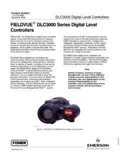
1 fieldvue DLC3010 Digital LevelControllerThe fieldvue DLC3010 Digital Level Controller is usedwith Level sensors to measure liquid Level , the Level ofthe interface between two liquids, or liquid specificgravity (density). Changes in Level or specific gravityexert a buoyant force on a displacer, which rotates atorque tube shaft. The Digital Level Controller convertsthis rotational motion to an electronic DLC3010 is a communicating,microprocessor-based instrument that can beconfigured to sense the Level , interface Level , ordensity of liquids. In addition to the normal function ofproviding a 4 to 20 milliampere current signal, theDLC3010, using HART communications protocol,gives easy access to information critical to processoperation. You can obtain information about theprocess, instrument, or sensor using the 475 or 375 Field Communicator. The DLC3010 can be used inanalog or HART Digital signaling mode with theEmerson Automation Solutions DeltaV connection for HART communication may bemade at any point in the field wiring that meets theHART impedance requirements.
2 Configuration,calibration, diagnostics, parameter review, signalmonitoring and alert monitoring are all availableW7977-2through the HART protocol. Information from the fieldcan be integrated into control systems or be receivedon a single loop DLC3010 Digital Level Controller is designed todirectly replace standard pneumatic and electroniclevel transmitters. It mounts on a wide variety of Fisher249 caged and cageless Level Digital Level ControllerD102727X012 Product : DLC3010 August 2017 DLC3010 Digital Level ControllerD102727X012 Product : DLC3010 August 2017 2 DLC3010 Digital Level Controller SpecificationsAvailable ConfigurationsDLC3010 Digital Level Controller :Mounts on caged and cageless 249 sensors. Seetables 4 and 5 and sensor : TransmitterCommunications Protocol: HARTI nput SignalLevel, Interface, or Density: Rotary motion of torquetube shaft proportional to changes in liquid Level ,interface Level , or density that change the buoyancyof a Temperature: Interface for 2- or 3-wire 100 ohm platinum RTD for sensing processtemperature, or optional user-entered targettemperature to permit compensating for changes inspecific gravityOutput SignalAnalog: 4 to 20 milliamperes DC (Jdirectaction increasing Level , interface, or densityincreases output; or Jreverse action increasinglevel, interface, or density decreases output)High saturation: mALow saturation: mAHigh alarm: mALow Alarm: mAOnly one of the above high/low alarm definitions isavailable in a given configuration.
3 NAMUR NE 43compliant when high alarm Level is : HART 1200 Baud FSK (frequency shift keyed)HART impedance requirements must be met toenable communication. Total shunt impedanceacross the master device connections (excluding themaster and transmitter impedance) must be between230 and 600 ohms. The transmitter HART receiveimpedance is defined as:Rx: 42K ohms and Cx: 14 nFIn point-to-point configuration, analog and digitalsignalling are available. The instrument may bequeried digitally for information, or placed in Burstmode to regularly transmit unsolicited processinformation digitally. In multi-drop mode, the outputcurrent is fixed at 4 mA, and only digitalcommunication is LevelController(1)w/ 3-Inch249W, Usinga 14-inchDisplacerw/ All Other249 SensorsIndependentLinearity$ ofoutput span$ ofoutput span$ ofoutput spanHysteresis< ofoutput span- - -- - -Repeatability$ of fullscale output$ ofoutput span$ ofoutput spanDead Band< ofinput span- - -- - -Hysteresis plusDeadband- - -< ofoutput span< ofoutput spanNOTE: At full design span, reference To lever assembly rotation : At effective proportional band (PB)<100%,linearity, dead band, repeatability, power supplyeffect, and ambient temperature influence arepotentially derated by the factor (100%/PB)Operating InfluencesPower Supply Effect: Output changes < of fullscale when supply varies between minimum andmaximum voltage specifications.
4 -continued-Table of ContentsDLC3010 Specifications of Operation Level Sensor Specifications Level Sensors Information Insulator Digital Level Controller Digital Level ControllerD102727X012 Product : DLC3010 August 2017 3 DLC3010 Digital Level Controller Specifications (continued)Transient Voltage Protection: The loop terminals areprotected by a transient voltage suppressor. Thespecifications are as follows:Pulse WaveformMax VCL(Clamping Voltage) (V)Max IPP(Pulse Peak@ Current) (A)Rise Time(ms)Decay to50% (ms) : s = microsecondAmbient Temperature: The combined temperatureeffect on zero and span without the 249 sensor is lessthan of full scale per degree Kelvin over theoperating range -40 to 80_C (-40 to 176_F)Process Temperature: The torque rate is affected bythe process temperature (see figure 1). The processdensity may also be affected by the Density: The sensitivity to error in knowledgeof process density is proportional to the differentialdensity of the calibration.
5 If the differential specificgravity is , an error of specific gravity units inknowledge of a process fluid density represents 10%of CompatibilityMeets EN 61326 1:2013 and EN 61326 2 3:2006 Immunity Industrial locations per Table 2 of EN 61326 1 and Table of EN 61326 2 3. Performance is shown in table 1 below. Emissions Class A ISM equipment rating: Group 1, Class ASupply Requirements (See figure 3)12 to 30 volts DC ; mAInstrument has reverse polarity minimum compliance voltage of is requiredto guarantee HART compensation: for ambient parameter compensation: for processtemperature (requires user-supplied tables).Manual compensation: for torque tube rate at targetprocess temperature is MonitorsLinked to jumper-selected Hi (factory default) or Loanalog alarm signal:Torque tube position transducer: Drive monitor andsignal reasonableness monitorUser-configurable alarms: Hi-Hi and Lo-Lo Limitprocess alarmsHART-readable only:RTD signal reasonableness monitor: When RTDinstalledProcessor free-time in Non Volatile Memory alarms: Hi and Lo limit processalarms, Hi and Lo limit temperature alarms, Hi and Lolimit electronics temperature alarmsDiagnosticsOutput loop current meter specific gravity measurement in Level mode: usedto update specific gravity parameter to improveprocess measurementDigital signal-tracing capability: by review of troubleshooting variables , andBasic trending capability for PV, TV and Meter IndicationsLCD meter indicates analog output on a percent scalebar graph.
6 The meter also can be configured todisplay:Process variable in engineering units only. Percent range range alternating with process variable orProcess variable, alternating with process temperature(and degrees of pilot shaft rotation).Electrical ClassificationPollution Degree IV, Overvoltage Category II per IEC61010 clause dHazardous Area:CSA Intrinsically Safe, Explosion proof, Division 2,Dust Ignition proofFM Intrinsically Safe, Explosion proof,Non incendive, Dust Ignition proofATEX Intrinsically Safe, Type n, FlameproofIECEx Intrinsically Safe, Type n, FlameproofRefer to tables 8, 9, 10, and 11 for additional Housing:CSA Type 4 XFM NEMA 4 XATEX IP66 IECEx IP66-continued- DLC3010 Digital Level ControllerD102727X012 Product : DLC3010 August 2017 4 DLC3010 Digital Level Controller Specifications (continued)Other Classifications/CertificationsCUTR Customs Union Technical Regulations (Russia,Kazakhstan, Belarus, and Armenia)INMETRO National Institute of Metrology,Standardization, and Industrial Quality (Brazil)KGS Korea Gas Safety Corporation (South Korea)NEPSI National Supervision and Inspection Centrefor Explosion Protection and Safety ofInstrumentation (China)PESO CCOE Petroleum and Explosives SafetyOrganisation - Chief Controller of Explosives (India)TIIS Technology Institution of Industrial Safety(Japan)Contact your Emerson sales office or Local BusinessPartnerfor classification/certification specificinformationMinimum Differential Specific GravityWith a nominal degrees torque tube shaftrotation for a 0 to 100 percent change in liquid Level (specific gravity=1)
7 , the Digital Level Controller can beadjusted to provide full output for an input range of5% of nominal input span. This equates to a minimumdifferential specific gravity of with standardvolume 249 sensor specifications for standard displacervolumes and standard wall torque tubes. Standardvolume for 249C and 249CP is 980 cm3 (60 in3),most others have standard volume of 1640 cm3(100 in3).Operating at 5% proportional band will degradeaccuracy by a factor of 20. Using a thin wall torquetube, or doubling the displacer volume will eachroughly double the effective proportional proportional band of the system drops below50%, changing displacer or torque tube should beconsidered if high accuracy is a PositionsDigital Level Controller can be mounted right- orleft-of-displacer, as shown in figure orientation is normally with the couplingaccess door at the bottom, to provide properdrainage of lever chamber and terminalcompartment, and to limit gravitational effect on thelever assembly.
8 If alternate drainage is provided byuser, and a small performance loss is acceptable, theinstrument could be mounted in 90 degree rotationalincrements around the pilot shaft axis. The LCD metermay be rotated in 90 degree increments toaccommodate MaterialsCase and Cover: Low-copper aluminum alloyInternal: Plated steel, aluminum, and stainless steel;encapsulated printed wiring boards; Neodymium IronBoron MagnetsElectrical ConnectionsTwo 1/2-14 NPT internal conduit connections; one onbottom and one on back of terminal box. M20adapters insulator JMountings for Masoneilan,Yamatake and Foxboro/Eckhardt displacers availableJLevel Signature Series Test (Performance ValidationReport) available (EMA only) for instrumentsfactory-mounted on 249 sensor JFactoryCalibration: available for instrumentsfactory-mounted on 249 sensor, when application,process temperature and density(s) are suppliedJDevice is compatible with user-specified remoteindicatorOperating LimitsProcess Temperature: See table 3 and figure Temperature and Humidity: See belowConditionsNormalLimits(1)(2)Transpo rt andStorageLimits(1)NominalReference(1)Am bientTemperature-40 to 80_C(-40 to 176_F)-40 to 85_C(-40 to 185_F)25_C(77_F)AmbientRelativeHumidity0 to 95%,(non-condensing)0 to 95%,(non-condensing)40%1.
9 LCD meter may not be readable below -20_C (-4_F)2. Contact your Emerson sales office or Local Business Partner or application engineerif temperatures exceeding these limits are RatingUp to 2000 meters (6562 feet)WeightLess than Kg (6 lb)NOTE: Specialized instrument terms are defined in ANSI/ISA Standard - Process Instrument Digital Level ControllerD102727X012 Product : DLC3010 August 2017 5 Table 1. EMC Summary Results ImmunityPortPhenomenonBasic StandardTest LevelPerformanceCriteria(1)(2)EnclosureE lectrostatic discharge (ESD)IEC 61000 4 24 kV contact8 kV airARadiated EM fieldIEC 61000 4 380 to 1000 MHz @ 10V/m with 1 kHz AM at 80%1400 to 2000 MHz @ 3V/m with 1 kHz AM at 80%2000 to 2700 MHz @ 1V/m with 1 kHz AM at 80%ARated power frequencymagnetic fieldIEC 61000 4 860 A/m at 50 HzAI/O signal/controlBurstIEC 61000 4 41 kVASurgeIEC 61000 4 51 kV (line to ground only, each)BConducted RFIEC 61000 4 6150 kHz to 80 MHz at 3 VrmsANote: RTD wiring must be shorter than 3 meters ( feet)1.
10 A = No degradation during testing. B = Temporary degradation during testing, but is self recovering. Specification limit = +/- 1% of HART communication was considered as not relevant to the process and is used primarily for configuration, calibration, and diagnostic Digital Level ControllerD102727X012 Product : DLC3010 August 2017 6 Figure 1. Theoretical Reversible Temperature Effect on Common Torque Tube MaterialsTORQUE RATE REDUCTION(NORMALIZED MODULUS OF RIGIDITY)GnormTEMPERATURE (_C) RATE REDUCTION(NORMALIZED MODULUS OF RIGIDITY)TEMPERATURE (_F)N05500N06600N10276S3160050 100 150 200 250 300 350 400 450 500 550 600 650 700 750 : 1 Due to the permanent drift that occurs near and above 260_C (500_F), N05500 is not recommendedfor temperatures above 232_C (450_F).1120 40 60 80 100 120 140 160 180 200 220 240 260 280 300 320 340 360 380 400 420 DLC3010 Digital Level ControllerD102727X012 Product : DLC3010 August 2017 7 Featuresn Simplified Setup and Calibration For quick analogtransmitter replacement (4-20mA out only), theinstrument may be configured with default sensordata, zero Level Offset, differential process SG, andzero/span procedure only.