Transcription of PRODUCT GUIDE - Compustar
1 REVISION DATE20170822 DOCUMENT NUMBERNOTICE The manufacturer will accept no responsability for any electrical damage resulting from improper installation of this PRODUCT , be that either damage to the vehicle itself or to the installed device. This device must be installed by a certified technician. Please review the Installation GUIDE carefully before beginning any work. Patent No. 8,856,780 PRODUCT Data Solutions Inc. Patent No. 8,856,780 GETTING STARTEDWELCOMENEED HELP?Congratulations on the purchase of your FT-DC3 solution. You are now a few simple steps away from enjoying your new remote starter unit with enhanced features. Before starting your installation, please ensure that your FT-DC3 module is programmed with the correct fi rmware for your vehicle and that you carefully review the install 866 OF CONTENTSBox Contents3 Tach Programming Procedure4 remote Programming Procedure5 Valet Mode Programming Procedure6 Compatible Accessories7 Online Module Settings9 Module Diagnostics10 remote Starter Error Codes11 Module Reset Data Solutions Inc.
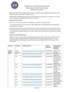
2 2017FT-DC3-HCPAGE 2 OF 12 Patent No. 8,856,780453216M6 FUNCTIONS DEFINED BY FIRMWAREAUTOMATICTRANSMISSIONCUT LOOPBOX CONTENTSFT-DAS - 4 PIN REDBLE - 4 PIN YELLOWRF PORT - 4 PIN BLUEDRONE - 4 PIN GRAYM6 - 6 PIN BLACKPROGRAMMING BUTTONM2 - 12 PIN BLACKM3 - 10 PIN WHITELED 1 LED 2FT-DAS SENSITIVTY ADJUSTMENT DIALWEBLINK PORT - 4 PIN BLACKHOOD SWITCHSTICKERSMODULECM-DC379310864125793 1081112641257931081113141215171819201664 125453216M5M401 GREEN BLACK DOT - LOCK (-) OUTPUT01 GREEN BLACK DOT - LOCK (-) OUTPUT02 BLUE BLACK DOT - UNLOCK (-) OUTPUT02 BLUE BLACK DOT - UNLOCK (-) OUTPUT03 RED/WHITE BLACK DOT - TRUNK RELEASE (-) OUTPUT03 RED/WHITE BLACK DOT - TRUNK RELEASE (-) OUTPUT04 GREEN/WHITE BLACK DOT - ARM (-) OUTPUT04 GREEN/WHITE BLACK DOT - ARM (-) OUTPUT05 GREEN/BLACK BLACK DOT - DISARM (-) OUTPUT05 GREEN/BLACK BLACK DOT - DISARM (-) OUTPUT06 BLUE/WHITE BLACK DOT - GWR (-) OUTPUT06 BLUE/WHITE BLACK DOT - GWR (-) OUTPUT07 BROWN BLACK DOT - SIREN (+)
3 OUTPUT07 BROWN BLACK DOT - SIREN (+) OUTPUT08 WHITE/PURPLE BLACK DOT - HORN (-) OUTPUT08 WHITE/PURPLE BLACK DOT - HORN (-) OUTPUT09 PURPLE/BLACK BLACK DOT - RAP SHUTDOWN (-) OUTPUT09 PURPLE/BLACK BLACK DOT - RAP SHUTDOWN (-) OUTPUT10 WHITE/BLACK BLACK DOT - HORN (-) OUTPUT10 WHITE/BLACK BLACK DOT - HORN (-) OUTPUT11 BROWN/BLACK BLACK DOT - GROUND WHEN ARMED (-) OUTPUT11 BROWN/BLACK BLACK DOT - GROUND WHEN ARMED (-) OUTPUT12 WHITE BLACK DOT - PARKING LIGHTS (-) OUTPUT01 BROWN SILVER DOT - BRAKE (+) INPUT02 BLACK/WHITE SILVER DOT - E-BRAKE (-) INPUT03 PURPLE SILVER DOT - DOOR (+) INPUT04 GREEN SILVER DOT - DOOR (-) INPUT05 PURPLE/WHITE SILVER DOT - TACH (-) INPUT06 WHITE/BLUE SILVER DOT - X-TRIGGER (-) INPUT07 GRAY SILVER DOT - HOOD (-) INPUT08 BLUE SILVER DOT - TRUNK (-) INPUT09 GRAY/BLACK SILVER DOT - GLOW PLUG (+) INPUT10 TAN SILVER DOT - EXT ALARM SENSOR (-) INPUTFUNCTIONS DEFINED BY FIRMWAREFUNCTIONS DEFINED BY FIRMWAREM3M2 RPS SENSOR - 4 PIN WHITESENSOR 2 - 4 PIN GREENALARM LED - 2 PIN WHITETEMP SENSOR - 2 PIN BLUEBATTERY - 2 PIN WHITEM5 - 6 PIN BLUEM4 - 20 PIN BLACK2 XBOX CONTENTS - 1 OF 1M14281357601 ORANGE - ACCESSORY (+)01 ORANGE - ACCESSORY (+)02 RED - POWER (30A)02 RED - POWER (30A)03 PURPLE - STARTER (+)03 PURPLE - STARTER (+)04 PINK/WHITE - PROG.
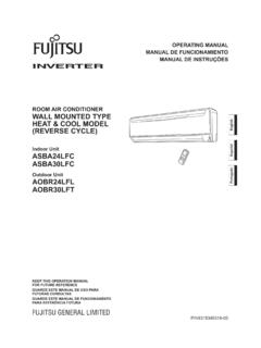
4 RELAY #4 - IGNITION 2 (+) (DEFAULT)04 PINK/WHITE - PROG. RELAY #4 - IGNITION 2 (+) (DEFAULT)05 PINK - IGNITION (+)05 PINK - IGNITION (+)07 RED - POWER (30A)07 RED - POWER (30A)08 BLACK - GROUND08 BLACK - GROUNDM106 WHITE - PROG. RELAY #5 (10A) - PARKING LIGHTS (+) (DEFAULT)06 WHITE - PROG. RELAY #5 (10A) - PARKING LIGHTS (+) (DEFAULT)M1 - 8 PIN Data Solutions Inc. 2017FT-DC3-HCPAGE 3 OF 12 Patent No. 8,856,78001 ENGINESTARTSTOPOFFACCONSTARTSTARTSTART 02 03 04 05 06 TACH PROGRAMMING PROCEDURE - 1 OF 1 START vehicle for 15 and hold the brake and release the module s programming button. (OR if the remotes are already programmed to the vehicle, press and hold the start button of the remote for seconds.)Wait, LED 2 will fl ash GREEN. (See the Module Diagnostics page)Release the brake Programming Procedure Data Solutions Inc. 2017FT-DC3-HCPAGE 4 OF 12 20170822>>0102 ENGINESTARTSTOPOFFACCONSTARTON03>>040506 >>0708 ENGINESTARTSTOPOFFACCONSTARTOFF09 AFTERMARKET remote PROGRAMMING PROCEDURE - 1 OF 1 WARNING: Program aftermarket remotes before usage.
5 A maximum of four [4x] aftermarket remotes per restriction. Complete next step within 7 ignition ON five times [5x OFF/ON] Light will flash once [1x].This step is only required for the ANT-1 WFMX & ANT-2 WFMX antennas. Press and release the antenna button. The antenna s leds will turn solid restriction. Complete next step within 5 seconds from previous once [1x] on LOCK button of aftermarket Light will flash once [1x].To program additional remotes: repeat steps 4 to 6 using each additional , Parking Light will flash twice [2x].Turn ignition to OFF remote Programming Procedure Patent No. 8,856,780>> 01 02 ENGINESTARTSTOPOFFACCONSTARTON 03 04 05 ENGINESTARTSTOPOFFACCONSTARTOFF 06 >> VALET MODE PROGRAMMING PROCEDURE - 1 OF 1 NOTE: In Valet Mode, the remote starter is not functional. Keyless entry, Lock and Unlock will remain functional. See RF kit user manual for alternate valet mode restriction. Complete next step within 7 ignition ON twice [2x OFF/ON] and release the BRAKE pedal three times [3x].
6 Parking Light will fl ash once [1x] then will fl ash twice [2x].Set ignition to OFF Mode Programming Procedure exit valet mode: repeat steps 1 to Data Solutions Inc. 2017FT-DC3-HCPAGE 6 OF 12 Patent No. 8,856, Data Solutions Inc. 2017FT-DC3-HCPAGE 7 OF 12 20170822 COMPATIBLE ACCESSORIES - 1 OF 2 MODULETELEMATIC PORTDRONE(NC)TELEMATIC KIT (accessory sold separately)10111213141516123456789 WEBLINK MOBILE (accessory sold separately) MOBILE DEVICE PORTOBDII CONNECTOR4 PIN BLACK CABLEMODULE WEBLINK PORTOBDII CONNECTORWEBLINK CABLE (required accessory sold separately)WEBLINK CABLECOMPUTERUSB PORT4 PIN BLACK CABLEMODULE WEBLINK Patent No. 8,856, Data Solutions Inc. 2017FT-DC3-HCPAGE 8 OF 12 20170822 COMPATIBLE ACCESSORIES - 2 OF 2RF KITRF KIT (accessories sold separately)ANTENNAMODULERF PORTTEMPERATURE SENSORTEMPERATURE SENSOR (accessories sold separately) MODULE2 PIN BLUE07 BROWN BLACK DOT - SIREN (+) OUTPUTREDBLACKSIRENALARM LEDFT-DASMODULE12 PIN BLACKMODULE2 PIN WHITEMODULE4 PIN REDALARM KIT (accessories sold separately) Patent No.
7 8,856,780 ONLINE MODULE SETTINGS - 1 OF 1 WEB PROGRAMMABLE MENUSDESCRIPTIONMENU 1 remote StarterRS related confi guration optionsMENU 2 Doorlock OptionsConvenience feature confi guration optionsMENU 3 Security OptionsAlarm activation and settingsMENU 4 AUX function assignmentsSet transmitter AUX buttons controlsMENU 5 Programmable outputs (POC)Set actions for programmable outputsMENU 6 Pulse Timer Output Confi guration (PTO)Set duration for pulse timer outputs (if used)MENU 7 Input Confi gurationsSet inputs for Auto by fi rmware/Data/AnalogMENU 8 Output Confi gurationsSet outputs for Auto by fi rmware/Data/AnalogProgramming options are avaible through Weblink and Weblink Mobile Data Solutions Inc. 2017FT-DC3-HCPAGE 9 OF 12 Patent No. 8,856,780 MODULE DIAGNOSTICS - 1 OF 1 TEST MODULELED 1 STATUSDIAGNOSTICIDURING MODULE PROGRAMMINGF lashing REDM issing/wrong information from fi rmware or REDM odule waiting for more vehicle GREENA dditional steps required to complete module GREEN then OFFM odule correctly activity or module already TACH PROGRAMMING1 GREEN fl ashTach signal programmed in Analog2 GREEN fl ashesTach signal programmed in Data3 RED fl ashesNo tach signal detected4 RED fl ashesSystem is in valet mode5 RED fl ashesTach set for VTS.
8 No tach programming required6 RED fl ashesTach set for assumed start . No tach programming requiredIIIDURING remote STARTF lashing REDM odule incorrectly REDM odule incorrectly GREENM odule correctly programmed and GREEN then OFFR eset in ground when running status from remote IGNITION OFFF lashing REDM odule incorrectly programmed or REDM odule not programmed. Waiting for more vehicle GREENF alse ground when running status from remote GREEN then OFFR eset in at rest and ready for a remote start Data Solutions Inc. 2017FT-DC3-HCPAGE 10 OF 12 Patent No. 8,856,780 remote STARTER ERROR CODES - 1 OF 1 remote STARTER ERROR CODES:NOTES[X] NUMBER OF PARKING LIGHT FLASHESDIAGNOSTICIWARNING: The following applies only when the parking lights are connected and supported by the running. 02 Key in ignition at ON a remote starter failure, the parking lights will fl ash three [3x] times, then will fl ash [X] number times to indicate an error code.
9 See is is brake is ON. 06 Hood is reservation is OFF. (Manual transmission only)08 Tach vehicle is moving (VSS).10 System is in Valet Mode. 11 CAN communication failure12RS not synchronized. Start vehicle with OEM key for 15 sec before trying a new RS STARTER SHUTDOWN ERROR CODES:NOTES[Y] NUMBER OF PARKING LIGHT FLASHESDIAGNOSTICIWARNING: The following applies only when the parking lights are connected and supported by the tach signal is brake is the engine shuts down after a remote starter sequence: Press and hold the Trunk button and the Start button at the same time for seconds when using a 1-WAY remote . OR Press once [1x] on button 4 when using a 2-WAY remote . The parking lights will fl ash four [4x] times, then will fl ash [Y] number times to indicate an error code. See brake is ON. 04 Hood is RPM limiter is plug timeout is moving (VSS).08N/A09N/A10 Door is communication failure during RS not synchronized.
10 Start vehicle with OEM key for 15 sec before trying a new RS is not error, board overheat Data Solutions Inc. 2017FT-DC3-HCPAGE 11 OF 12 Patent No. 8,856,780>> 01 02 03 04 05 06 07 08 >> MODULE RESET PROCEDURE - 1 OF 1 The following procedure resets the module programming to the vehicle. It does not reset any settings confi gured all connectors from module except the M1 BLACK 8-pin connector and the M4 BLACK 20-pin the M1 BLACK 8-pin connector and the M4 BLACK 20-pin AND HOLD the module s programming button while connecting the M1 BLACK 8-pin connector and the M4 BLACK 20-pin , LED 1 will flash RED. RELEASE programming 1 will turn RED for 2 RESET all programming to follow procedure may result with a DTC or a CHECK ENGINE error Data Solutions Inc. 2017FT-DC3-HCPAGE 12 OF 12 20170822