Transcription of Professional Series Four-Way
1 Professional Series Four-Way Studio Monitors 4340 For Bi-Amplification 4341 With High Level Network Accurate, smooth reproduction from 35 to 20,000 Hz, *3 dB 44 dB SPL at 30 feet with a l-milliwatt input 101 dB SPL at 10 feet at one-half rated power input Components: low frequency loud speaker, lo-inch midrange loudspeaker, high frequency compression driver with horn/lens assemblyand ultra-highfrequencytransducer Balance controls located behind the removable grille Oiled walnut or textured gray enclosure The 4340 and 4341 Studio Monitors The 4340 and 4341 represent an extension of the research and development effort that produced the 4350 Studio Monitor, JBL s top system, which uses dual low frequency drivers. These new monitors accurately reproduce the full range of fundamentals and overtones in music at sound pressure levels approximating thoseof an original performance. The exceptionally smooth wide-band reproduction, clarity, transient response and low distortion of the 4340 and 4341 result from total integration of the components that make up the Four-Way system so that each transducer reproduces only that portion of the audio spectrum for which it is specifically designed.
2 Deliberately restricting the operat- ing bandwidth of the individual drivers results in,maximization of each unit s transient re- sponse. Another benefit of bandwidth limita- tion is that each driver operates only in the region of the audio spectrum through which it exhibits controlled sound distribution, thus a dispersion pattern for the complete system is achieved which is ideal for studio use. The passive frequency dividing network supplied with the 4341 controls the acoustic output of all the individual transducers. The 4340 is provided with a passive network for only the high and ultra-high frequency transitions, and is fitted with terminals for bi-amplification of the low frequency transition. Low Frequency Loudspeaker The low frequency loudspeaker is mounted in a ported enclosure having an internal volume of cubic driver features extreme, solid low frequency repro- duction with smooth response well past its crossover unit is energized by a 13-pound magnetic assembly housing an Alnico V magnet.
3 The assembly concen- trates a magnetic field having a flux density of 12,000 gauss in the voice coil gap. The 4-inch edgewound copper ribbon voice coil is hand wound on a heat resistant support. The support is affixed to a rigid cone having optimum mass, density and rigidity for excep- tional transient response and maximum efficiency consistent with the bandwidth of the driver. Midrange Loudspeaker The smooth performance and instantaneous transient response of the lo-inch midrange loudspeaker is largely responsible for the outstanding instrumental clarity, vocal defini- tion and dimensional accuracy of the system. Its closed magnetic assembly, weighing 6% pounds, concentrates all the energy of an Alnico V magnet in the voice coil gap. The 3-inch edgewound copper ribbon voice coil is suspended within a powerful magnetic field having a flux density of 10,000 gauss. The Integrally stlffened cone IS terminated with an exclusive JBL ring compliance that allows long excursions while malntalnlng linear travel High Frequency Compression Driver The htgh frequency compresslon driver provtdes smooth, accurate response and IS capable of dellvenng the high power output levels required in monitor applications The closed magnetic assembly IS energized by an Alnico V magnet, weighs 10 pounds and achieves a flux density of 19,000 gauss in the voice co11 gap A ring of pure silver deposited on the circumference of the pole piece main- talns uniform Impedance through the highest frequencies extending the bandwidth of the driver The diaphragm, pneumatically formed of 002-Inch thick aluminum foil stock.
4 IS driven by a 1 edgewound aluminum ribbon voice co11 The wavefront emerging from the diaphragm IS directed through the concentric channels of a phasing plug pnor to distribution by the horn/lens assembly Horn/Lens Assembly Output from the high frequency compresslon driver IS distributed through a controlled pattern by the horn/lens assembly The horn IS formed of a ngld casting to eliminate spun- ous resonance The exponential taper rate of the horn controls the expansion of the wavefront provldlng proper acoustic loading of the driver diaphragm and determines the vertical dispersion pattern of the assembly The acoustic lens functions In a manner analogous to a dlvergent optical lens Its 11 plates, set at a precise angle to the enclosure baffle panel, provide controlled propagation of high frequency acoustic energy in the honzontal plane Ultra-High Frequency Transducer Overtones above 9000 Hz are reproduced by a compression driver and diffraction horn - specifically designed for reproduction and dispersion of energy at the extreme high end of the audio spectrum.
5 The compression driver consists of a 3%pound magnetic assembly energized by an Alnico V magnet. The edgewound aluminum ribbon voice coil, suspended within a field having a flux density of 16,500 gauss is affixed to a heat resistant support bonded to a ring dia- phragm pneumatically formed of .0022-inch thick aluminum foil. Output from the dia- phragm IS directed through the Integral diffraction horn, which produces the unit s wide high frequency dispersion pattern. Frequency Dividing Network The 4341 is provided with a high level, passive frequency dividing network for the three isequipped with a similar network for the high and ultra- high frequency transitions only. In each case, the circuitry has been designed with consi- deration for the various performance charac- teristics of the drivers and their location on the enclosure baffle panel. The network has been designed for continuous high power application; capacitors are non-inductive, non-polarized types with high AC current capacity, and special inductors are used to minimize power losses within the network.
6 Each inductor is calibrated on a sensitive electronic bridge and its value set precisely. The 4340 is provided with input terminals for the two amplifiers of a bi-amplified instal- i lation. A special circuit card providing the precise crossover characteristics for the 4340 is available for use in the JBL 5231 or 5232 Electronic Frequency Dividing Network. / Frequency response of the 4340 and 4341 taken with %-Wave band pinli noise. Measured resoonse contour of a tvolcal svstem averaaed throuah an inclusive arc of 600 in the horizontal - and 30 in the vertical &nes dooes not devke more than 2 dB from the above curve. : , ,: ; : Conventional electronic networks can be i used, but they may not have the exact frequency and filter slope characteristics required for optimum performance of the system. Enclosure In keeping with current trends in studio design that encourage creativity, JBL studio monitor enclosures feature contemporary styling and are offered in two finishes, each with a complementary grille color.
7 The enclo- sure, however, contributes much more than striking appearance. The low frequency loud- speaker is housed in a chamber having an internal volume of cubic mid- range loudspeaker is enclosed in a separate, Isolated sub-chamber havrng an Internal volume of 3 cubic feet The Internal volume of the acoustrc chambers and physrcal con- frguratron of the ducted ports are carefully calrbrated to properly load the low frequency and midrange loudspeakers for optimum bass response and to control cone excursron, thus minrmizing drstortron and maxrmrzrng power handling capacity of the dnvers To elimrnate resonance, the enclosure IS con- structed of dense l-inch stock wrth a 15.~1~ baffle panel, all faints are carefully lock mitered and glued the back, side, top and bottom panels are lined with acoustrc damp- rng matenal and are each stiffened by multiple braces glued and screwed to the panel and to the adjacent surfaces of the enclosure Test Parameters The accompanying graph and specifications were compiled from measurements made under standard laboratory test conditions.
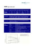
8 The complete loudspeaker system, including the enclosure, was mounted flush in the center of a large, flat baffle in an anechoic environment. Calibrated condenser micro- phones were suspended at a measured distance from the sound source, sufficiently out of the near field. All associated electronic equip- ment was checked and calibrated before tests were run. rille ,;._ Black fabric with the gray finish; -. Dark Blue fabric with walnut : -., 75 Watts steady state at 8 ohms ;ior& .I. ( m) in a room volume of 2000 .: ,f cu. ft. ( ma) with M rated power z , ~~~~~~~~~ .. 37% ~23Y$xi9%~ deep . ,, .( - 1; 95x60x50cmdeep ! ,, ..:b 3. Response Sensitivity3 No less than -3 dE? at 60 hori- zontal and 300 vertical to 16 kHz dB SPL measured at 10 ft. ( m) with l-Watt Input averaged from 100 to 1000 Hz Accessorrf Network, single channel 5232 Electronic Frequency Dividing L Network, dual channel ,; Distortion 1 / 2 Power, 99 dB SPL/lO ft.)
9 [ ), Srngle Frequency 44 dB SPL measured at 30 ft. (9 1 m) wrth I-m&watt input averaged from 100 to 1000 Hz 1% or less third harmonic generation from 35 to 1500 Hz 2% or less third harmonic generation above 1500 Xz 525140 Crossover Card, required for the low frequency transition of the 4340. Sound pressure levels produced by the 4340 or 4341 may cause permanent hearing loss The suggested maxrmum exposure IS 115 dBA for no more than 15 minutes (Department of Labor Bulletin #334) abov&2000 Hz ma; be considerably greater than that of other systems with htgher EIA Sensltlvlfy rat,ngs The 52 5140 crossover card , stalled I a JBL electr~ ,c freciuencv d,wd, a]