Transcription of Professional Weather Center - AcuRite
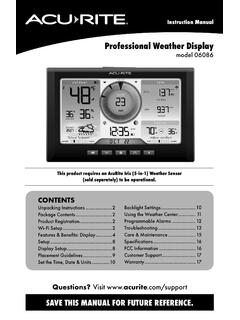
1 Instruction Manual Professional Weather Center model 01536 / 8900123 CONTENTS Unpacking Instructions .. 2 Package Contents .. 2 Product Registration .. 2 Features & Benefits: 3 Features & Benefits: 4 Setup .. 7 5-in-1 Sensor Setup .. 7 Display 8 Set the Time, Date & 9 Backlight 9 Placement 5-in-1 Sensor Using the Weather Center ..12 IT FEELS LIKE 46 OUTSIDE PC Weather Underground ..13 Rainfall Weather Ticker ..15 Programmable Care & 20 20 22 FCC Information .. 22 Customer Support .. 23 23 Questions? Contact Customer Support at (877) 221-1252 or visit SAVE THIS MANUAL FOR FUTURE REFERENCE. 2 Congratulations on your new AcuRite product. To ensure the best possible product performance, please read this manual in its entirety and retain it for future reference. Unpacking Instructions Remove the protective film that is applied to the LCD screen prior to using this product.
2 Locate the tab and peel off to remove. Package Contents 1. Display with Tabletop Stand 2. 5-in-1 Sensor 3. Sensor Mounting Bracket 4. Mounting Hardware 5. Power Adapter 6. USB Cable 7. 4 Alkaline Batteries 8. Instruction Manual PRODUCT MUST BE REGISTERED IMPORTANT TO RECEIVE WARRANTY SERVICE PRODUCT REGISTRATION Register online to receive 1 year warranty protection 3 Features & Benefits 10 11 2 1 8 5 6 43 5-in-1 SENSOR 1. Rainfall Collector Funnel 2. Solar Cell Panel Converts sunlight into power to run internal aspirating fan. Internal Aspirating Fan (not shown) Draws ambient air into sensor to reduce solar radiation heating, resulting in more accurate temperature measurement. 3. A-B-C Switch ID code that must match display s A-B-C switch to ensure units synchronize. 4. Battery Compartment 7 9 5. Temperature & Humidity Sensors (internal) 6.
3 Mounting Point 7. Wind Speed Anemometer 8. Wind Direction Vane 9. Mounting Bracket 10. Mounting Hardware Includes 5 anchors & the following screws: Qty Diameter Length 5 #4 3/4 1 #4 1/2 1 #6 1/2 11. Debris Filter Pre-installed to prevent debris from entering the rain gauge. 13 Bln .. totol 12 days since last rain Features & Benefits Display 12 3 1 4 5 635 734 33 32 8 31 9 30 10 29 11 28 12 13 27 14 26 15 25 24 IT FEELS LIKE 46 OUTSIDE 23 22 21 20 1918 17 16 4 5 ox 1. Current Wind Direction 2. Previous 2 Wind Directions 3. Seasonal Display Heat Index calculation displays whentemperature is 80 F (27 C) or Point calculation displays whentemperature is 79 F (26 C) or chill calculation displays when temperature is 40 F (4 C) or lower. 4. Button For momentary backlight and dimmer settings. 5. Current Wind Speed 6.
4 Rainfall Displays most recent rainfall total (today, this week or this month). 7. Rainfall History Displays historical rainfall totals (see page 14). 8. Indoor Indicator Indicates indoor (display unit) conditions are being shown. 9. Current Temperature for #8 or #12 Arrow icon indicates direction temperature is trending. 10. Add-On Sensor Signal Strength If applicable (see page 13). 11. Auto-Cycle Indicator Indicates auto-cycle mode is enabled. If applicable (see page 13). 12. Add-On Sensor Indicator If applicable (see page 13). 13. Humidity Level IndicatorIndicates a high, low, or ideal humidity comfort level. 14. Current Humidity for #8 or #12 Arrow icon indicates direction humidity is trending. 15. Date 16. Button Press to view rainfall records (#6 and #7). 17. Display Low Battery Icon 18. Peak Wind SpeedHighest speed from the last 60 minutes. 19. Button For setup preferences and manuallycycling through Weather Ticker messages(when display is not connected toadditional sensors).
5 For manually cyclingadd-on sensor data (when display isconnected to additional sensors). 20. Button For setup preferences. 21. Clock 22. Button For setup preferences and manually cycling through Weather Ticker messages (when display is not connected to additional sensors). For manually cycling add-on sensor data (when display is connected to additional sensors). 23. Button For alarm setup preferences. 24. Weather TickerTM Streams real-time data (see page 15). 25. 5-in-1 Sensor Signal Strength 26. Sensor Low Battery Icon 27. Icon Indicates display is in auto-dimming brightness mode (see page 9). 28. Barometric Pressure Arrow icon indicates direction pressure is trending. 29. Average Wind SpeedAverage wind speed over the past 2 minutes. 30. 12 to 24 Hour Weather Forecast Self-Calibrating Forecasting pulls data from your 5-in-1 sensor to generate your personal forecast. 31. Learning Mode IconDisappears after Weather forecast self-calibration is complete (see page 12).
6 32. High/Low Humidity RecordsHighest and lowest outdoor humidity recorded since midnight. 33. Current Outdoor HumidityArrow icon indicates direction humidity is trending. 34. High/Low Temperature RecordsHighest and lowest outdoor temperature recorded since midnight. 35. Current Outdoor TemperatureArrow icon indicates direction temperature is trending. 6 Back of Display 123 4 ############DEVICE ID01536-RX Refroidissement olien Point De Ros e Dew Point Wind Chill RX : DC 3x AA AC/DC ADAPTER INPUT : 100-240AC 50-60Hz OUTPUT: 250mA CAN RSS-Gen/CNR-GenMODEL : 01536 CDI 6 7 5 89 BACK OF DISPLAY 1. Plug-in for Power Adapter 2. Plug-in for USB Cable 3. Integrated KeyholeFor easy wall mounting. 4. DEVICE ID 12 digit unique ID required for online connectivity functions. 5. Backup Battery Compartment 6. A-B-C Switch ID code that must match 5-in-1 sensor s A-B-C switch to ensure units synchronize.
7 7. CLEAR RECORD / RESET ButtonPress and HOLD for 8 seconds to clear all records. Press and HOLD for 10 seconds for full reset to factory defaults. 8. Power Adapter 9. USB Cable for PC Connection 10. Battery Compartment Cover(not shown) 7 SETUP 5-in-1 Sensor Setup 1 Set the A-B-C Switch Locate the A-B-C switch inside the battery compartment. Set the A-B-C switch to A, B or C. You must select the same letter choices for both the sensor and the display in order for the units to synchronize. 2 Install or Replace Batteries Batteries MUST be installed for this product to operate. AcuRite recommends high quality alkaline or lithium batteries for the best product performance. Heavy duty or rechargeable batteries are not recommended. The 5-in-1 sensor requires lithium batteries in low temperature conditions. Cold temperatures can cause alkaline batteries to function A B C 1 A-B-C Switch Set to match display 2 Install Batteries 4 AA Batteries 3 Rain Gauge StabilizerRemove and discard NOTE: If add-on sensors are being used with the display (see page 12), set them up at this time.
8 If pairing more than one wireless sensor with the display, the A-B-C channel must differ between each add-on sensor. The display will automatically begin searching for add-on sensors during initial setup. 3 improperly. Use lithium batteries in the 5-in-1 sensor for temperatures below -4 F/-20 C. 1. Slide off the battery compartment cover. 2. Insert 4 x AA batteries into the battery compartment, as shown. Follow the polarity (+/-) diagram in the battery compartment. 3. Replace the battery cover. Remove Rain Gauge Stabilizer Locate and remove the rain gauge stabilizer (plastic tab) taped into the bottom of the sensor. The rain gauge will not function until this is removed. 8 Display Setup 3 4 3 Batteries 3 AA Batteries 5-in-1 Sensor 2 Plug in Power Adapter A B C IMPORTANT: Batteries are a backup power source to preserve records in the event of a power outage. Power adapter is the recommended primary power source to enjoy the full functionality of this product.
9 PLEASE DISPOSE OF OLD OR DEFECTIVE BATTERIES IN AN ENVIRONMENTALLY SAFE WAY AND IN ACCORDANCE WITH YOUR LOCAL LAWS AND REGULATIONS. BATTERY SAFETY: Clean the battery contacts and also those of the device prior to battery installation. Remove batteries from equipment which is not to be used for an extended period of time. Follow the polarity (+/-) diagram in the battery compartment. Promptly remove dead batteries from the device. Dispose of used batteries properly. Only batteries of the same or equivalent type as recommended are to be used. DO NOT incinerate used batteries. DO NOT dispose of batteries in fire, as batteries may explode or leak. DO NOT mix old and new batteries or types of batteries (alkaline/standard). DO NOT use rechargeable batteries. DO NOT recharge non-rechargeable batteries. DO NOT short-circuit the supply terminals. 1 Set the A-B-C Switch The A-B-C switch is located inside the battery compartment.
10 It can be set to A, B or C. However, you must select the same letter choices for both the 5-in-1 Sensor and the display in order for the units to synchronize. Plug Power Adapter into Electric Outlet 21 A-B-C Switch set to match Write Down the DEVICE ID 12 digit unique ID needed for online connectivity functions. 24 C8 6E Install or Replace Backup Batteries (optional) Insert 3 x AA alkaline batteries into the battery compartment, as shown. Follow the polarity (+/-) diagram in the battery compartment. 4 Write Down DEVICE ID 12 digit number Install Backup 9 ox ox Set the Time, Date & Units The display will automatically enter SET MODE after the unit has powered on. Once in set mode, the preference you are currently setting will blink on the display. To adjust the currently selected (flashing) item, press and release the or buttons (press and HOLD to fast adjust). To save your adjustments, press and release the button again to adjust the next preference.