Transcription of Programmable Logic Controllers, Basic Level …
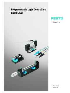
1 Programmable Logic Controllers Basic Level Textbook TP 301. Festo Didactic 093311 en 1 13:44:12. B-II. Authorised applications and liability The Learning System for Automation and Technology has been devel- oped and prepared exclusively for training in the field of automation. The training organization and/or trainee shall ensure that the safety precau- tions described in the accompanying Technical documentation are fully observed. Festo Didactic hereby excludes any liability for injury to trainees, to the training organization and/or to third parties occurring as a result of the use or application of the station outside of a pure training situation, un- less caused by premeditation or gross negligence on the part of Festo Didactic. Order No.: 093311. Description: SPS LB GS. Designation: 1-GB. Edition: 08/2002. Layout: , OCKER Ingenieurb ro Graphics: D. Schwarzenberger, OCKER Ingenieurb ro Authors: R. Bliesener, , ffler, B. Plagemann, , , A. Winter Copyright by Festo Didactic GmbH & Co.
2 , D-73770 Denkendorf 2002. The copying, distribution and utilization of this document as well as the communication of its contents to others without expressed authorization is prohibited. Offenders will be held liable for the payment of damages. All rights reserved, in particular the right to carry out patent, utility model or ornamental design registrations. Parts of this training documentation may be duplicated, solely for training purposes, by persons authorised in this sense. TP301 Festo Didactic B-III. Preface The Programmable Logic controller represents a key factor in industrial automation. Its use permits flexible adaptation to varying processes as well as rapid fault finding and error elimination. This textbook explains the design of a Programmable Logic controller and its interaction with peripherals. One of the main focal points of the textbook deals with the new interna- tional standard for PLC programming, the EN 61131-3 (IEC-61131-3).
3 This standard takes into account expansions and developments, for which no standardised language elements existed hitherto. The aim of this new standard is to standardise the design, functionality and the programming of a PLC in such a way as to enable the user to easily operate with different systems. In the interest of continual further improvement, all readers of this book are invited to make contributions by way suggestions, ideas and con- structive criticism. August 2002 The authors TP301 Festo Didactic B-IV. TP301 Festo Didactic B-V. Table of Contents Chapter 1 Automating with a PLC B-1. Introduction B-1. Areas of application of a PLC B-2. Basic design of a PLC B-5. The new PLC standard EN 61131 (IEC 61131) B-8. Chapter 2 Fundamentals B-11. The decimal number system B-11. The binary number system B-11. The BCD code B-13. The hexadecimal number system B-13. Signed binary numbers B-14. Real numbers B-14. Generation of binary and digital signals B-15.
4 Chapter 3 Boolean operations B-19. Basic Logic functions B-19. Further Logic operations B-23. Establishing switching functions B-25. Simplification of Logic functions B-28. Karnaugh-Veitch diagram B-30. TP301 Festo Didactic B-VI. Chapter 4 Design and mode of operation of a PLC B-33. Structure of a PLC B-33. Central control unit of a PLC B-35. Function mode of a PLC B-37. Application program memory B-39. Input module B-41. Output module B-43. Programming device/Personal computer B-45. Chapter 5 Programming of a PLC B-47. Systematic solution finding B-47. EN 61131-3 (IEC 61131-3) structuring resources B-50. Programming languages B-54. Chapter 6 Common elements of programming languages B-57. Resources of a PLC B-57. Variables and data types B-60. Program B-70. Chapter 7 Function block diagram B-85. Elements of function block diagram B-85. Evaluation of networks B-85. Loop structures B-87. Chapter 8 Ladder diagram B-89. Elements of ladder diagram B-89.
5 Functions and function blocks B-92. Evaluation of current rungs B-93. TP301 Festo Didactic B-VII. Chapter 9 Instruction list B-95. Instructions B-95. Operators B-96. Functions and function blocks B-97. Chapter 10 Structured text B-99. Expressions B-99. Statements B-101. Selection statements B-103. Iteration statements B-106. Chapter 11 Sequential function chart B-111. Introduction B-111. Elements of sequential function chart B-111. Transitions B-120. Steps B-123. Example B-135. Chapter 12 Logic control systems B-139. What is a Logic control system B-139. Logic control systems without latching properties B-139. Logic control systems with memory function B-145. Edge evaluation B-148. Chapter 13 Timers B-153. Introduction B-153. Pulse timer B-154. Switch-on signal delay B-156. Switch-off signal delay B-158. TP301 Festo Didactic B-VIII. Chapter 14 Counter B-161. Counter functions B-161. Incremental counter B-161. Decremental counter B-165. Incremental/decremental counter B-167.
6 Chapter 15 Sequence control systems B-169. What is a sequence control system B-169. Function chart to IEC 60848 B-169. Chapter 16 Commissioning and operational safety of a PLC B-175. Commissioning B-175. Operational safety of a PLC B-177. Chapter 17 Communication B-183. The need for communication B-183. Data transmission B-183. Interfaces B-184. Communication in the field area B-185. Appendix A Bibliography of illustrations B-187. B Bibliography of literature B-189. C Guidelines and standards B-191. D Glossary B-193. E Index B-199. TP301 Festo Didactic B-1. Chapter 1. The PLC in automation technology Introduction The first Programmable Logic Controller (PLC) was developed by a group of engineers at General Motors in 1968, when the company were looking for an alternative to replace complex relay control systems. The new control system had to meet the following requirements: Simple programming Program changes without system intervention (no internal rewiring).
7 Smaller, cheaper and more reliable than corresponding relay control systems Simple, low cost maintenance Subsequent development resulted in a system, which enabled the sim- ple connection of binary signals. The requirements as to how these sig- nals were to be connected were specified in the control program. With the new systems it became possible for the first time to plot signals on a screen and to file these in electronic memories. Since then, three decades have passed, during which the enormous progress made in the development of microelectronics did not stop short of Programmable Logic controllers. For instance, even if program optimi- sation and thus a reduction of required memory capacity initially still rep- resented an important key task for the programmer, nowadays this is hardly of any significance. Moreover, the range of functions has grown considerably. 15 years ago, process visualisation, analogue processing or even the use of a PLC as a controller, were considered as Utopian.
8 Nowadays, the support of these functions forms an integral part of many PLCs. The following pages in this introductory chapter outline the Basic design of a PLC together with the currently most important tasks and applica- tions. TP301 Festo Didactic B-2. Chapter 1. Areas of application of a PLC. Every system or machine has a controller. Depending on the type of technology used, controllers can be divided into pneumatic, hydraulic, electrical and electronic controllers. Frequently, a combination of differ- ent technologies is used. Furthermore, differentiation is made between hard-wired Programmable ( wiring of electro-mechanical or electronic components) and Programmable Logic controllers. The first is used pri- marily in cases, where any reprogramming by the user is out of the question and the job size warrants the development of a special control- ler. Typical applications for such controllers can be found in automatic washing machines, video cameras, and cars.
9 However, if the job size does not warrant the development of a special controller or if the user is to have the facility of making simple or inde- pendent program changes, or of setting timers and counters, then the use of a universal controller, where the program is written to an elec- tronic memory, is the preferred option. The PLC represents such a uni- versal controller. It can be used for different applications and, via the program installed in its memory, provides the user with a simple means of changing, extending and optimising control processes. TP301 Festo Didactic B-3. Chapter 1. Fig. : Example of a PLC application The original task of a PLC involved the interconnection of input signals according to a specified program and, if "true", to switch the correspond- ing output. Boolean algebra forms the mathematical basis for this opera- tion, which recognises precisely two defined statuses of one variable: "0". and "1" (see also chapter 3).
10 Accordingly, an output can only assume these two statuses. For instance, a connected motor could therefore be either switched on or off, controlled. This function has coined the name PLC: Programmable Logic control- ler, the input/output behaviour is similar to that of an electro- magnetic relay or pneumatic switching valve controller; the program is stored in an electronic memory. However, the tasks of a PLC have rapidly multiplied: Timer and counter functions, memory setting and resetting, mathematical computing opera- tions all represent functions, which can be executed by practically any of today's PLCs. TP301 Festo Didactic B-4. Chapter 1. The demands to be met by PLC's continued to grow in line with their rapidly spreading usage and the development in automation technology. Visualisation, the representation of machine statuses such as the control program being executed, via display or monitor. Also controlling, the facility to intervene in control processes or, alternatively, to make such intervention by unauthorised persons impossible.