Transcription of PS10 SERIES - Viking Corp
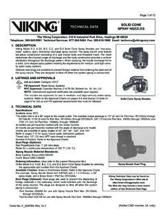
1 PS10 SERIES . PRESSURE SWITCH. UL, cUL, and CSFM Listed, FM and LPC Approved, NYMEA. Accepted, CE Marked Dimensions: " (9,6cm)W x " (8,1cm)D x " (10,7cm)H. Conduit Entrance: Two knockouts provided for 1/2" conduit. Individual switch compartments and ground screws suitable for dissimilar voltages. Enclosure: Cover - Die-cast with textured red powdercoat finish, single cover screw and rain lip. Base - Die-cast Pressure Connection: Nylon 1/2" NPT Male Factory Adjustment: 4 - 8 PSI (0,27 - 0,55 BAR). Differential: 2 PSI (0,13 BAR) typical Maximum System Pressure: 300 PSI (20,68 BAR). Switch Contacts: SPDT (Form C) Amps at 125/250 VAC, Amps at 30 VDC. Ordering Information One SPDT in PS10-1, Two SPDT in PS10-2. Model Description Stock No. Environmental Specifications: PS10-1 Pressure switch with one set 1340103 NEMA 4/IP66 Rated Enclosure - indoor or outdoor when used SPDT contacts with NEMA 4 conduit fittings. PS10-2 Pressure switch with two sets 1340104 Temperature range: -40 F to 140 F (-40 C to 60 C) SPDT contacts Service Use: Hex Key 5250062 Automatic Sprinkler NFPA-13.
2 Cover Tamper Switch Kit 0090200 One or two family dwelling NFPA-13D. Tamper Residential Occupancy up to four stories NFPA-13R. Cover incorporates tamper resistant fastener that requires a special key for National Fire Alarm Code NFPA-72. removal. One key is supplied with each device. For optional cover tamper switch kit, order Stock No. 0090200. See bulletin #5401200 PSCTSK. Installation The Potter PS10 SERIES Pressure Actuated Switches are designed for the into alarm port piping on the input side of retard chamber and electrically detection of a waterflow condition in automatic fire sprinkler systems of connect PS10 to control unit that provides a retard to compensate for surges. particular designs such as wet pipe systems with alarm check valves, dry Insure that no unsupervised shut-off valves are present between the alarm pipe, preaction, or deluge valves. The PS10 is also suitable to provide a check valve and PS10. low pressure supervisory signal; adjustable between 4 and 15 psi (0,27 and Method 2: When using the PS10 for local bell application or with a control 1,03 BAR).
3 That does not provide a retard feature - the PS10 must be installed on the alarm 1. Apply Teflon tape to the threaded male connection on the device. outlet side of the retard chamber of the sprinkler system. (Do not use pipe dope) Testing: Accomplished by opening the inspector's end-of-line test valve. 2. Device should be mounted in the upright position (threaded connection down). Allow time to compensate for system or control retard. 3. Tighten the device using a wrench on the flats on the device. Note: Method 2 is not applicable for remote station service use, if there is an unsupervised shut-off valve between the alarm check valve and the PS10. Wiring Instructions 1. Remove the tamper resistant screw with the special key provided. Wet System With Excess Pressure 2. Carefully place a screwdriver on the edge of the knockout and Connect PS10 into alarm port piping extending from alarm check valve. sharply apply a force sufficient to dislodge the knockout plug.
4 See Fig 9 Retard provisions are not required. Insure that no unsupervised shut-off 3. Run wires through an approved conduit connector and affix the connector valves are present between the alarm check valve and the PS10. to the device. Testing: Accomplished by opening the water by-pass test valve or the 4. Connect the wires to the appropriate terminal connections for the inspector's end-of-line test valve. When using end-of-line test, allow time service intended. See Figures 2,4,5, and 6. See Fig 7 for two switch, one for excess pressure to bleed off. conduit wiring. Dry System Testing Connect PS10 into alarm port piping that extends from the intermediate The operation of the pressure alarm switch should be tested upon completion chamber of the alarm check valve. Install on the outlet side of the in-line of installation and periodically thereafter in accordance with the applicable check valve of the alarm port piping. Insure that no unsupervised shut-off NFPA codes and standards and/or the authority having jurisdiction valves are present between the alarm check valve and the PS10.
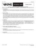
5 (manufacturer recommends quarterly or more frequently). Testing: Accomplished by opening the water by-pass test valve. Wet System Note: The above tests may also activate any other circuit closer or water Method 1: When using PS10 and control unit with retard - connect PS10 motor gongs that are present on the system. Potter Electric Signal Company, LLC St. Louis, MO Phone: 866-956-0988/Canada 888-882-1833 PRINTED IN USA MFG. #5400928 - Rev D-1 page 1 OF 3. 12/10. PS10 SERIES . PRESSURE SWITCH. Dimensions Switch Clamping Plate Terminal Fig. 1 Fig. 2. GROUND N G. MI. SCREWS CO. IN. ADJUSTMENT [ ]. KNOB [ ]. NG. OI DWG# 923-3. 1/2" NPT TG. OU. [ ] [ ]. An uninsulated section of a single conductor [ ] [ ] should not be looped around the terminal and serve as two separate connections. The wire NOTE: To prevent leakage, apply Teflon tape sealant to male threads only. must be severed, thereby providing supervision of the connection in the event that the wire DWG# 930-1 becomes dislodged from under the terminal.
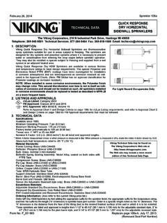
6 Typical Sprinkler Applications Fig. 3. WET SYSTEM WITH WET SYSTEM WITHOUT DRY SYSTEM. EXCESS PRESSURE EXCESS PRESSURE. PS10. PS10 PS10. WATER WATER WATER. MOTOR MOTOR MOTOR. GONG GONG GONG. RBVS CHECK. WET RBVS DRY VALVE RBVS. SYSTEM WET SYSTEM. ALARM SYSTEM ALARM. CHECK ALARM CHECK. CHECK RETARD VALVE. VALVE. VALVE. WATER WATER WATER. OS & Y BY-PASS BY-PASS OS & Y BY-PASS. OS & Y. VALVE VALVE VALVE VALVE VALVE. VALVE. DWG. #923-2AA. Closing of any shutoff valves between the alarm check valve and the PS10 will render the PS10. inoperative. To comply with NFPA-72 any such valve shall be electrically supervised with a supervisory switch such as Potter Model RBVS. Low Pressure Signal Connection Waterflow Signal Connection Local Bell For Waterflow Connection Fig. 4 Fig. 5 Fig. 6. TO FIRE ALARM PANEL NEGATIVE DC. TO FIRE ALARM PANEL OR NEUTRAL AC. EOLR EOLR BELL. LINE LOAD. POSITIVE DC. OR HOT AC. DWG# 928-1 DWG# 928-2 DWG# 928-3. PRINTED IN USA MFG.
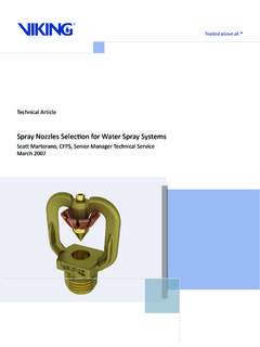
7 #5400928 - Rev D-1 page 2 OF 3. 12/10. PS10 SERIES . PRESSURE SWITCH. One Conduit Wiring Switch Operation Removing Knockouts Fig. 7 Fig. 8 Fig. 9. Terminal W/ PRESSURE APPLIED. Break out thin section of divider to provide path for wires C: Common when wiring both switches from one conduit entrance. 1: Closed when installed under normal system C. pressure. 2: Open when installed under normal system pressure. Closes on C 1 2. pressure drop. Use for low pressure supervision. Terminal W/O PRESSURE APPLIED. 1: Open with no pressure supplied. Closes upon C. detection of pressure. Use for waterflow indication. 2: Closed with no DWG#928-5. C 1 2. DWG# 928-4. pressure applied. DWG#928-6. Installation must be performed by qualified personnel and in Do not tighten by grasping the switch enclosure. Use wrenching accordance with all national and local codes and ordinances. flats on the bushing only. Failure to install properly could damage Shock hazard.
8 Disconnect power source before servicing. the switch and cause improper operation resulting in damage to Serious injury or death could result. equipment and property. Read all instructions carefully and understand them before To seal threads, apply Teflon tape to male threads only. Using starting installation. Save instructions for future use. Failure to joint compounds or cement can obstruct the pressure port inlet read and understand instructions could result in improper and result in improper device operation and damage to equipment. operation of device resulting in serious injury or death. Do not over tighten the device, standard piping practices apply. Risk of explosion. Not for use is hazardous locations. Serious injury or death could result. Engineer/Architect Specifications Pressure Type Waterflow Switch Pressure type waterflow switches; shall be a Model PS10 as Pressure switch shall have one or two form C contacts, switch contact manufactured by Potter Electric Signal Company, St Louis MO.
9 , rating Amps at 125/250 VAC, Amps at 30 VDC. and shall be installed on the fire sprinkler system as shown and or Pressure type waterflow switches shall have two conduit entrances specified herein. one for each individual switch compartment to facilitate the use of Switches shall be provided with a NPT male pressure connection dissimilar voltages for each individual switch. and shall be connected to the alarm port outlet of; Wet Pipe Alarm The cover of the pressure type waterflow switch shall be Zinc die-cast Valves, Dry Pipe Valves, Pre-Action Valves, or Deluge Valves. The with rain lip and shall attach with one tamper resistant screw. The pressure switch shall be actuated when the alarm line pressure reaches Pressure type waterflow switch shall be suitable for indoor or outdoor 4 - 8 PSI (0,27 - 0,55 BAR). service with a NEMA 4/IP66 rating. Pressure type waterflow switches shall have a maximum service The pressure type waterflow switch shall be UL Ulc and CSFM listed, pressure rating of 300 PSI (20,68 BAR) and shall be factory adjusted FM and LPC approved and NYMEA accepted.
10 To operate on a pressure increase of 4 - 8 PSI (0,27 - 0,55 BAR). PRINTED IN USA MFG. #5400928 - Rev D-1 page 3 OF 3. 12/10.