Transcription of Quick Start - download.msi.com
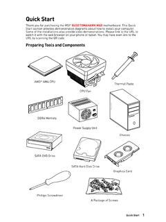
1 1 Quick StartDDR4 MemoryGraphics CardSATA Hard Disk DriveSATA DVD DrivePhillips ScrewdriverChassisPower Supply UnitA Package of ScrewsThermal PasteQuick StartThank you for purchasing the MSI Z390-A PRO motherboard. This Quick Start section provides demonstration diagrams about how to install your computer. Some of the installations also provide video demonstrations. Please link to the URL to watch it with the web browser on your phone or tablet. You may have even link to the URL by scanning the QR Tools and ComponentsIntel LGA 1151 CPUCPU Fan2 Quick a Processor1236457893 Quick StartInstalling DDR4 StartConnecting the Front Panel SWPOWER SWPOWER LED+ power LED-HDD LEDHDD LEDRESET SWJFP1 HDD LEDHDD LED -HDD LED + power LED - power LED + power LED12109+++----+ power LEDHDD LEDR eset SwitchReservedPower SwitchJFP11 HDD LED +2 power LED +3 HDD LED -4 power LED -5 Reset Switch6 power Switch7 Reset Switch8 power Switch9 Reserved10No Pin5 Quick StartBAT1 Installing the Motherboard126 Quick StartInstalling SATA Start1 Installing a Graphics StartConnecting Peripheral Devices9 Quick StartConnecting the power StartPower On142311 ContentsContentsQuick Start .
2 1 Preparing Tools and Components ..1 Installing a Processor ..2 Installing DDR4 memory ..3 Connecting the Front Panel Header ..4 Installing the Motherboard ..5 Installing SATA a Graphics Card ..7 Connecting Peripheral Devices ..8 Connecting the power Connectors ..9 power ..13 Package contents ..18 Block Diagram ..19 Rear I/O Panel ..20 LAN Port LED Status Ports Configuration ..20 Realtek Audio Console ..21 Overview of Components ..23 CPU Socket ..25 DIMM Slots ..26 PCI_E1~6: PCIe Expansion Slots ..27 SATA1~6: SATA 6Gb/s Connectors ..27M2_1: Slot (Key M) ..28 JTPM1: TPM Module Connector ..28 JFP1, JFP2: Front Panel Connectors ..29 JCOM1: Serial Port Connector ..29 JTBT1: Thunderbolt Add-on Card Connector ..29 CPU_PWR1, ATX_PWR1, PCIE_PWR1: power Connectors ..30 JUSB3~4: USB Gen1 Connectors ..31 JUSB1~2: USB Connectors ..32 JLPT1: Parallel Port Connector ..32 CPU_FAN1, PUMP_FAN1, SYS_FAN1~5: Fan Connectors.
3 33 JAUD1: Front Audio Connector ..34 JCI1: Chassis Intrusion Connector ..34 JBAT1: Clear CMOS (Reset BIOS) Jumper ..35 JOC1: Front OC Button Connector ..3512 ContentsJRGB1: RGB LED connector ..36EZ Debug LED ..36 Installing OS, Drivers & Utilities ..37 Installing Windows 10 ..37 Installing Drivers ..37 Installing Utilities ..37 MYSTIC LIGHT ..38 Device LED effect control screen ..38 BIOS Setup ..41 Entering BIOS Setup ..41 Resetting BIOS ..42 Updating BIOS ..42EZ Mode ..43 Advanced Mode ..45 SETTINGS ..46 Advanced ..46 Boot ..53 Security ..53 Save & Exit ..54OC ..56M-FLASH ..62OC PROFILE ..63 HARDWARE MONITOR ..64 RAID Configuration ..65 Enabling Intel Rapid Storage Technology ..65 Creating RAID Volume ..66 Removing a RAID Volume ..67 Resetting Disks to Non-RAID ..68 Rebuilding RAID Array ..69 Installing RAID Driver ..70 Installing Intel Rapid Storage Technology Software.
4 70 Intel Optane Memory Configuration ..71 System Requirements ..71 Installing the Intel Optane memory ..71 Removing the Intel Optane memory ..73 Troubleshooting ..74 Regulatory Notices ..7513 SpecificationsSpecificationsCPUS upports Intel Core 9000 Series family/ 8th Gen Intel Core / Pentium Gold / Celeron processors for LGA 1151 socket* Please go to for more compatibility Z390 ChipsetMemory y4x DDR4 memory slots, support up to 128GB* ySupports DDR4 4400(OC)/ 4300(OC)/ 4266(OC)/ 4200(OC)/ 4133(OC)/ 4000(OC)/ 3866(OC)/ 3733(OC)/ 3600(OC)/ 3466(OC)/ 3400(OC)/ 3333(OC)/ 3300(OC)/ 3200(OC)/ 3000(OC) / 2800(OC)/ 2666/ 2400/ 2133 MHz* ySupports Dual-Channel mode ySupports non-ECC, un-buffered memory ySupports Intel Extreme Memory Profile (XMP)* Please refer for more information on compatible Slot y2x PCIe x16 slots, support x16/ x4 mode y4x PCIe x1 slots y1 x slot with E key for Integrated Intel Wireless-AC (CNVi)
5 Module onlyOnboard Graphics y1x VGA port, supports a maximum resolution of 2048x1536@50Hz, 2048x1280@60Hz, 1920x1200@60Hz y1x DVI-D port, supports a maximum resolution of 1920x1200@60Hz y1x DisplayPort, supports a maximum resolution of 4096x2304@60 HzMulti-GPU ySupports 2-Way AMD CrossFire TechnologyStorageIntel Z390 Chipset y6x SATA 6Gb/s ports* y1x slot (Key M) Supports up to PCIe x4 and SATA 6Gb/s, 2242/ 2260/ 2280/ 22110 storage devices Intel Optane Memory Ready** The SATA2 will be unavailable when installing SATA device into slot. ** Before using Intel Optane memory modules, please ensure that you have updated the drivers and BIOS to the latest version from MSI on next page14 SpecificationsContinued from previous pageRAIDI ntel Z390 Chipset ySupports RAID 0, RAID1, RAID 5 and RAID 10 for SATA storage devicesLAN y1x Intel I219-V Gigabit LAN controllerUSB yIntel Z390 Chipset 2x USB Gen2 (SuperSpeed USB 10 Gbps) ports (1x Type-A port and 1x Type-C port) on the back panel 6x USB Gen1 (SuperSpeed USB) ports (2 Type-A ports on the back panel, 4 ports available through the internal USB connectors) 6x USB (High-speed USB) ports (2 Type-A ports on the back panel, 4 ports available through the internal USB connectors)** The CNVI_1 and JUSB2 share the same bandwidth.
6 Please refer to page 32 for yRealtek ALC892 Codec High Definition AudioBack Panel Connectors y1x PS/2 keyboard/ mouse combo port y2x USB Type-A ports y1x VGA port y1x DVI-D port y1x DisplayPort y1x USB Gen2 Type-A port y1x USB Gen2 Type-C port y1x LAN (RJ45) port y2x USB Gen1 Type-A ports y6x audio jacksContinued on next page15 SpecificationsContinued from previous pageInternal Connectors y1x 24-pin ATX main power connector y1x 8-pin ATX 12V power connector y1x 6-pin ATX 12V power connector y6x SATA 6Gb/s connectors y2x slots (1 M-Key slot,1 E-Key slot) y2x USB Gen1 connectors (supports additional 4 USB Gen1 ports) y2x USB connectors (supports additional 4 USB ports) y1x 4-pin CPU fan connector y1x 4-pin Water Pump connector y5x 4-pin system fan connectors y1x Front panel audio connector y2x System panel connectors y1x Chassis Intrusion connector y1x 4-pin RGB LED connector y1x Serial Port connector y1x Clear CMOS jumper y1x Parallel port connector y1x TPM module connector y1x thunderbolt Add-on card connector y1x Front OC button connectorI/O ControllerNUVOTON NCT6797 Controller ChipHardware Monitor yCPU/System temperature detection yCPU/System fan speed detection yCPU/System fan speed controlForm Factor yATX Form Factor y12 in.
7 X in. ( cm x cm)BIOS Features y1x 128 Mb flash yUEFI AMI BIOS yACPI , SMBIOS yMulti-languageContinued on next page16 SpecificationsContinued from previous pageSoftware yDrivers yDRAGON CENTER yMYSTIC LIGHT yCPU-Z MSI GAMING yIntel Extreme Tuning Utility yGoogle Chrome ,Google Toolbar, Google Drive yNorton Internet Security SolutionDragon Center Features yOC Performance yHardware Monitor yEyerest yLAN Manager yLive UpdatePlease refer to for more Features yAudio Audio Boost yNetwork Intel LAN with Network Manage Intel CNVi Ready yStorage Turbo yFan Pump Fan Smart Fan Control yLED Mystic Light Extension (RGB) EZ DEBUG LEDC ontinued on next page17 SpecificationsContinued from previous pageSpecial Features yProtection PCI-E Steel Armor PCI-E Steel Slot yPerformance Core Boost OC Genie Multi GPU-CrossFire Technology DDR4 Boost USB with type A+C Intel Turbo USB Gen2 yVR VR Ready yBIOS Click BIOS 518 Package contentsPackage contentsPlease check the contents of your motherboard package.
8 It should contain:MotherboardZ390-A PROC ableSATA 6Gb/s Screw1I/O Shield1 Case Badge1 VIP Card1 Application DVDD river DVD1 DocumentationQuick Installation Guide1 ImportantIf any of the above items are damaged or missing, please contact your Diagram Block Diagram LPC Bus2 Channel DDR4 Memory2 x USB Gen21 x 6 x USB Express BusP/S2 Mouse / KeyboardAudio JacksDMI chipsetCPUNV6797 Super I/ORealtekALC892 PCI Express BusDisplayPortDVI-DVGAPCIe x1 slotPCIe x1 slot6 x SATA 6Gb/sx1x1 PCIe x1 slotx1 PCIe x1 slotx1 Switch6 x USB Gen1 PCI Express Busx41x (E Key for Intel CNVi module only) IntelI219-V20 Rear I/O PanelRear I/O PanelPS/2 LANDVI-DVGAA udio PortsUSB Gen1 Type-AUSB Gen2 Type-ADisplayPortUSB Gen2 Type-CLink/ Activity LEDS tatusDescriptionOffNo linkYellowLinkedBlinkingData activitySpeed LEDS tatusDescriptionOff10 Mbps connectionGreen100 Mbps connectionOrange1 Gbps connectionLAN Port LED Status TableAudio Ports ConfigurationAudio PortsChannel2468 Line-InLine-Out/ Front Speaker Out Rear Speaker Out Center/ Subwoofer Out Side Speaker Out Mic In( : connected, Blank: empty)21 Rear I/O PanelRealtek Audio ConsoleAfter Realtek Audio Console is installed.
9 You can use it to change sound settings to get better sound experience. yDevice Selection - allows you to select a audio output source to change the related options. The check sign indicates the devices as default. yApplication Enhancement - the array of options will provide you a complete guidance of anticipated sound effect for both output and input device. yMain Volume - controls the volume or balance the right/left side of the speakers that you plugged in front or rear panel by adjust the bar. yAdvanced Settings - provides the mechanism to deal with 2 independent audio streams. yJack Status - depicts all render and capture devices currently connected with your computer. yConnector Settings - configures the connection popup dialogWhen you plug into a device at an audio jack, a dialogue window will pop up asking you which device is current jack corresponds to its default setting as shown on the next page.
10 ImportantThe pictures above for reference only and may vary from the product you purchased. Jack StatusConnector Settings Device SelectionMain VolumeApplication EnhancementAdvanced Settings22 Rear I/O PanelAudio jacks to headphone and microphone diagramAudio jacks to stereo speakers diagramAudio jacks to speakers diagramAUDIO INPUTRearFrontSideCenter/SubwooferAUDIO INPUT23 Overview of ComponentsBAT1 Overview of ComponentsDIMMA1 CPU_PWR1 CPU SocketPCI_E1 SYS_FAN1 PCI_E2 JBAT1 PCI_E3 PCI_E4 PCI_E5 PCI_E6 JTPM1 DIMMA2 DIMMB1 DIMMB2 CPU_FAN1 PUMP_FAN1 PCIE_PWR1 SYS_FAN5 SYS_FAN4 JCOM1 SYS_FAN2 JRGB1 ATX_PWR1 JUSB4 JUSB3M2_1 CNVI_1 JTBT1 JOC1 JCI1 JUSB1 SATA 1 2 SATA 3 4 SATA 5 6 JFP2 SYS_FAN3 JFP1 JLPT1 JUSB2 JAUD124 Overview of ComponentsComponent ContentsPort NamePort TypePageCPU_FAN1, PUMP_FAN1, SYS_FAN1~5 Fan Connectors33 CPU_PWR1, ATX_PWR1, PCIE_PWR1 power Connectors30 CPU SocketLGA 1151 Socket25 DIMMA1/A2/B1/B2 DIMM Slots26 JAUD1 Front Audio Connector34 JBAT1 Clear CMOS Jumper35 JCI1 Chassis Intrusion Connector34 JCOM1 Serial Port Connector29 JFP1, JFP2 Front Panel Connectors29 JLPT1 Parallel Port Connector32 JOC1 Front OC Button Connector35 JRGB1 RGB LED connector36 JTBT1 Thunderbolt Add-on Card Connector29 JTPM1 TPM Module Connector28 JUSB1~2 USB Connectors32 JUSB3~4 USB Gen1 Slot (Key M)28 PCI_E1~6 PCIe Expansion Slots27 SATA1~6 SATA 6Gb/s Connectors2725 Overview of ComponentsCPU SocketIntroduction to the LGA 1151 CPUThe surface of the LGA 1151 CPU has two notches and a golden triangle to assist in correctly lining up the CPU for motherboard placement.