Transcription of Rack and Pinion Drive – Calculation and Selection
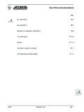
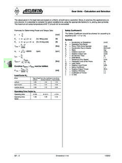
1 Dimensions in mmZD 11/2012 ChapterRacks Helical m = ZA-30 m = 2 ZA-31 m = 3 ZA-32 m = 4 ZA-33 m = 5 ZA-34 m = 6 ZA-35 m = 8 ZA-36 m = 10 ZA-37 m = 12 ZA-38 Racks Straight m = 1 ZB-36 m = ZB-37 m = 2 ZB-38 m = ZB-39 m = 3 ZB-40 m = 4 ZB-41 m = 5 ZB-42 m = 6 ZB-43 m = 8 ZB-44 m = 10 ZB-45 m = 12 ZB-46 Integrated Racks m = 2 ZC-15 m = 3 ZC-16 m = 4 ZC-17 p = 5 mm ZC-18 p = 10 mm ZC-19 p = mm ZC-20 Calculation , Instruction ZD-2 Calculation Example Travelling Operation ZD-3 Lifting Operation ZD-4 Actual size of modular gearing according to DIN 867 ZD-5 rack and Pinion Drive Calculation and SelectionDimensions in mmZD 21/2012 rack and Pinion Drive Calculation and SelectionThe values given in the load table are based upon uniform, smooth operation, KH = and reliable grease lubrication.
2 Since, in practice, the applications are very diverse, it is important to consider the given conditions by using appropriate factors SB, KA, LKH and fn (see below). Formulas for Determining the Tangential Forcea = [m/s ]Fu = m g + m a (for lifting axle) [kN] 1000Fu = m g + m a (for driving axle) [kN] 1000Fu perm. = [kN] Formula dimensions see page ZD-3 The Condition Fu < Fu perm. Must be Factor KADrive Type of load from the machines to be driven Uniform Medium Shocks Heavy ShocksUniform Shocks Shocks Coefficient SBThe safety coefficient should be allowed for according to experience (SB = to ). tbFu TabKA SB fn LKH Life-Time Factor fn considering of the peripheral speed of the Pinion and Continuous Daily MonthlyPeripheral Speed of Gearingm/sec m/min 30 60 from 90 3 120 to 180 10 300 Load Distribution Factor LKH The linear load distribution factor considers the contact stress, while it describes unintegrated load distribution over the tooth width (LKH = KH ).
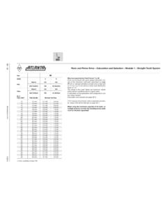
3 LKH = for counter bearing, Torque Supporter = for preloaded bearings on the output shaft ATLANTA HT, HP and E servo-worm gear unit, BG bevel-gear unit = for unpreloaded bearings on the output shaft ATLANTA B servo-worm gear unitDimensions in mmZD 31/2012 Your CalculationValues Given Travelling Operation Mass to be Moved m = kgSpeed v = m/sAcceleration Time tb = sAcceleration Due to Gravity g = m/s2 Coefficient of Friction = Load Factor KA = Life-Time Factor fn = Safety Coefficient SB = Linear Load LKH = Distribution FactorCalculation Process Results a = a = = m/s2 Fu = m g +m a ; Fu = = kNPermissible Feed Force Fu Tab Fu = ; Fu zul.
4 /per. = = kNConditionFu > Fu ; kN > kN = > fulfilled rack and Pinion Drive - Calculation and Selection tbCalculation ExampleValues Given Travelling Operation Mass to be Moved m = 820 kgSpeed v = 2 m/sAcceleration Time tb = 1 sAcceleration Due to Gravity g = m/s2 Coefficient of Friction = Factor KA = Factor fn = (cont. lubrication) Safety Coefficient SB = Load LKH = FactorCalculation Process Results a = a = = 2 m/s2Fu = m g +m aFu = 820 +820 2 = kNAssumed feed force: rack C45, ind.
5 Hardened, straight tooth, module 3, Pinion 16 MnCr5, case hardened, 20 teeth, page ZB-40 with Futab = kNFu = ; Fu = = kNConditionFu > Fu ; kN > kN = > fulfilled Result: rack 27 30 101 Page ZB-13 Pinion 24 35 220 Page ZB-23 case hardened x tbFuTabKA SB fn LKH TabKA SB fn LKH 1000100010001000 Dimensions in mmZD 41/2012 Your CalculationValues Given Lifting Operation Mass to be Moved m = kgSpeed v = m/sAcceleration Time tb = sAcceleration Due to Gravity g = m/s Load Factor KA = Life-Time Factor fn = Safety Coefficient SB = Linear Load LKH = Distribution FactorCalculation Process Resultsa = a = = m/s Fu = m g+m a Fu = = kNPermissible Feed Force Fu tab Fu = ; Fu = = kNConditionFu > Fu.
6 KN > kN => fulfilled Calculation ExampleValues Given Lifting Operation Mass to be Moved m = 300 kgSpeed v = m/sAcceleration Time tb = sAcceleration Due to Gravity g = m/s Load Factor KA = Life-Time Factor fn = (Cont. Lubrication) Safety Coefficient SB = Load LKH = FactorCalculation Process Results a = a = = 4 m/s Fu = m g+m a Fu = 300 +300 4 = kNAssumed feed force: rack C45, ind. hardened, helical, module 2, Pinion 16 MnCr5, case hardened, 20 teeth, page ZA-31 with Futab = 12 kNFu = ; Fu = = kNConditionFu > Fu ; kN > kN => fulfilled Result: rack 29 20 105 Page ZA-7 Pinion 24 29 520 Page ZA-24 rack and Pinion Drive - Calculation and Selection tbxx TabKA SB fn LKH Fu TabKA SB fn LKH