Transcription of Radio Crane Control Systems - HubbellDirect.com
1 Hubbell Industrial Controls, September 2000 Replaces: Brochure 31100 of June 96 Catalog Sheet 31100 AC Compact RadioCatalog Sheet 31100 Diagnostic DisplayCatalog Sheet 31132 License-Free RadioRadioCraneControlSystemsHubbell Radio Remote Control SystemsHUBBELLH ubbell Radio Control Systems use the latestmicro-controller technology and ultra reliableManchester II (bi-phase) digital FM signalcoding. Each Radio Control system operates on alicensed frequency in the 72 to 76 MHz or the450 to 470 MHz security of any remote Control system is ofthe utmost importance. Hubbell Radio controlsystems security is enhanced through multiplechecks before any function can becomeoperational: The received signal must be of the properfrequency. The received message must have the properaddress and must be in the correct format.
2 The receiver calculated CRC code must beidentical to the CRC code calculated by thetransmitter and sent as part of each message. The preceding items must be met and alltransmitter lever switches must be centeredbefore the Crane Main Contactor can beenergized. To continue or change an energized function,requires the receipt of a valid message prior to timeout of the message timer. If novalid message is received, the system turns offall outputs. Two separate watchdog timers assure thatall outputs are switched off in case of areceiver AC Compact Stylewith DC Compact Stylewith AC License-Free with Belt-Clip TransmitterHubbell Industrial Control SolutionsRadio Crane Control SystemsA typical Radio Crane Control system consists of a portable transmitter carried by theoperator, and a receiver installed on the Crane .
3 Each system operates on a licensedfrequency in the 72 to 76 MHz or the 450 to 470 MHz receiver is crystal controlled. A synthesized receiver is an option for 72 76 MHz. An 8-bit micro-controller, operating at MHz, decodes the signalcoming from the rf module and passes the output commands through the I/O boardsto the output ac receiver uses 120V ac Solid State Relay output modules. No interface relays areneeded for controllers up to and including size 4 contactors. An LED shows the status ofthe output module. A stepless, analog output module is available, as is a relay cardusing electro-mechanical output relays. Input modules monitor the status of the 120V acControl Power, Main Contactor, plus M, F, R for each output modules on the dc receiver are 270V dc Solid State Relays. No interfacerelays are needed for controllers up to and including size 5 contactors.
4 The outputmodule status is shown by LED s: red = output activated; green = output current modules monitor the status of the 250V dc Control Power, Main Contactor, plus M,F, R for each transmitter/receiver pair has their own unique 7 bit address code (the first sevenbits of the digital message). Unless the transmitter address and receiver address areidentical, the system will not respond to any command, regardless of the integrity is assured by use of an 8-bit Cyclic Redundancy Check (CRC)code. Cyclic redundancy check is a division performed in the transmitter logic,which produces a remainder that is transmitted last as the 8-bit check code. Thereceiver logic performs a like division on the received message (without the CRC) toproduce its own 8 bit CRC code. If the two CRC codes are identical, the receivedmessage will be decoded as a valid message and the appropriate outputs will beturned on or off, as crystal controlled transmitter uses an 8-bit micro-controller, operating at MHz, toscan the command switches.
5 All major function switches must be in the center or off position before the Crane Main Contactor can be energized. When the transmitter is on and the command switches are off or centered, then the transmitter actually sendsa stop command to the system. Motion can occur only with the removal of the stop command and the addition of a speed point/directional command within a certain timesequence. Using the key-switch to turn off the transmitter power causes the transmitter tosend five consecutive E-STOP messages before shutting switch position data is transmitted as a digital signal at the licensed frequency, usingManchester II coding. The digital message has a specific format and is repeated 2 to9 times per second. The repeat rate is programmable. The transmitter is turned offbetween messages to conserve battery life and rf spectrum.
6 This makes it possible tohave several transmitters operating in the same area, on the same frequency, withpractically no interference because of the different transmission rates. The unique addresscode of each transmitter and receiver assures that only the matching receiver responds tothe Radio commands. All other signals on the same frequency are use of Manchester II (bi-phase) digital FM signal coding makes the message lesssensitive to corruption from interference. Please consult Tech Info , page 2, for adetailed discussion on the message format and Manchester II DisplayModuleStandard Features For new and existing microprocessorbased Crane and locomotive controls 2 line x 20 character backlit LCDdisplay for message and time stamp English descriptions of faults Display mounted in receiver rack or onmicroprocessor unit Fault logging with local or remotedown load capability Control button for setting batterybacked real time clockTypical Fault MessagesStart-up & Run Mode Status/FaultsNORMAL OPERATION MSGOK MPS 16:21:56 POWER-UP WAITINGNO MSG 16:21:56 TROLLEY TX SW NOTCENTERED 16:21:56 BRIDGE M STUCK ONFAULT 16:21:56 BRIDGE M STUCK OFFFAULT 16:21:56 DIAG TEST OK NO MSGFROM TX 16:21:56 TIMED OUT NO MSGFROM TX 16:21.
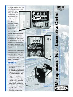
7 56 RUN RELAY STUCK OFFRUN FAULT 16:21:56 RUN RELAY STUCK ONRUN FAULT 16:21:56 RUN OUTPUT STUCK ONRESET FAULT 16:21:56 WATCHDOG MONITOR MCBFAULT 16:21:56 MCB SELF TEST RAMFAILURE 16:21 AC, 72 or 450 mHz, CompactStyle with Micro-ControllerHubbell Performance High speed microprocessor Bi-phase, digital signal transmissionIncreased Flexibility Very compact receiver Fits even the smallest craneInternal Diagnostics Run by microprocessor on internalprograms Run by microprocessor on commandsand I/O Power-up diagnostics Continuous monitoringOperational Status English language diagnostic displayTransmitter High speed microprocessor Compact, light weight Up to four lever switch controlfunctions Toggle switch and pushbutton DC, 72 or 450 mHz, CompactStyle with Micro-ControllerThe Hubbell Microprocessor Radio CraneControl Systems features a microcomputerwith status display and built-in diagnosticsalong with our high speed, digital,biphase modulation to provide reliable.
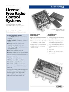
8 Efficient and economical operation ofelectric overhead cranes from a Easy to Maintain Self diagnosticsidentify problem areas via the statusdisplay. Fast Response High Speed data rateoffers fast, responsive operation. Frequency Conservation Up to foursystems can share the same radiofrequency, which also saves on spareparts requirements. Improved Control Remote controltakes the operator out of the cabproviding him with improved visibilityand total Control from a ground floorposition. Simple Operation Portable,lightweight transmitter is easier tooperate than manual cab AC, License-Freewith Micro-Controller System approved for operationunder FCC Part 15 rules no userlicense required. Digital FM signal exceptionalimmunity to noise. Security 6000+ address codesavailable. State of the art design surface mount,micro-controller electronics.
9 Auto power off extends battery life. Extremely compact and cost one of several single-speedtransmitters or a two-speed transmitter: Key-Ring - with 1 or 4 buttons Belt-Clip - with 1, 2, 3, 4, or 6 buttons Hand-Held - with 6 or 8 buttons Hand-Held -- with 8 two-speed transmitters are rated NEMA 3 forindoor/outdoor receivers with the number of outputrelays to match the transmitter flexible half wave antenna mountsdirectly to the receiver by BNCconnector. All receivers are rated NEMA4X for indoor/outdoor refer to Spec Sheet formore detailed information on Industrial Control SolutionsTypical 250V DC Output SectionBelt-ClipHand-HeldKey-RingJPS-100 -1M 2000 Printed in Edwards StreetMadison, Ohio 44057(440) 428-1161 Fax (440) 428-76354301 Cheyenne DriveArchdale, NC 27263(336) 434-2800 Fax (336) 434-2801 Hubbell IndustrialControls, subsidiary ofHubbell IncorporatedHubbell Industrial Control AC Compact StyleWeight ?
10 ? DC Compact StyleWeight ??SpecifcationsTypical to All SystemsSupply Voltage .. AC: 108 132V ac, 50/60 Hz. DC: 175 350 V dcInternal Power Requirements .. + dc, A & + dc, 2 A maxOperating Temperature .. 22 F ( 30 C) to 140 F (+60 C) Radio ReceiverFrequency Range .. 72 76 MHz or 450 470 MHzChannel Availability .. 30 @ 72 MHz, 8 protected, over 200 shared @ 450 MHzFrequency Stability .. 10 ppmSensitivity .. 1 v @ 20 dB quieting nominalData Reception .. compatible with Hubbell transmittersModulation .. Manchester II (bi-phase)Baud Rate .. 4800 bpsMessage Format .. preamble, sync, start flag, address, Control , CRC check codeControl SectionSingle board computer consisting of 80C31BH controller, 64k EPROM, EPLD contain-ing circuits for message synchronizing, and processor watchdogAC Output Section (Triac modules)Panel mounted mother-board to accommodate up to 24 triac ac input or output modulesIndicators.