Transcription of Random Thoughts from Chicago by Jim Brown Part 2
1 Syn-Aud-Con Newsletter11In the last newsletter (Vol 31, #2), I showed how very short lengths of wire connecting input shields to an equipment chassis could have enough inductance to couple significant radio frequency interference into audio equipment, and showed how one manufacturer had solved the problem. This time we ll look at other effective solutions. The European EMC directive, implemented in the late 1990 s, places limits on noise emissions from elec-tronic equipment sold in most European countries.
2 It caused a lot of manufacturers to get EMC religion, and gave new life to RF engineers working in labs dedicated to verifying compliance. The engineers, working in these labs and those specializing in designing for good EMC performance think in terms of RF immunity and computer/digital systems. Few have much practical experience with analog audio systems, and some of the design solutions they advance can cause us considerable grief - especially the treatment of cable shields. From an RF point of view, the shell of an XL con-nector looks like it should work as the extension of the cable shield.
3 For broadband RF immunity, it can be helpful to ground shields at every opportunity and carefully bond all grounded objects together at multiple points. Such a philosophy is the basis of the so-called mesh ground topology, and it can work well in installations where there s little difference in potential between grounds at opposite ends of the audio paths. But power system leakage currents cause enough power-related shield current to flow in most real world installations to couple noise into the sound system if both ends of a cable shield are grounded.
4 Since the 1930 s, engineers have known that audio frequency noise coupling will be minimized with single point (star) grounding, while radio frequency noise coupling is minimized with multi-point (mesh) ground-ing. The solution is simple -- the shield of a balanced audio cable is connected to the shielding enclosure at the driving source, and to the shielding enclosure at the receiving end through a capacitor. It was easy to do this in the 40 s, when RF signals higher than 30 MHz were rarely encountered.
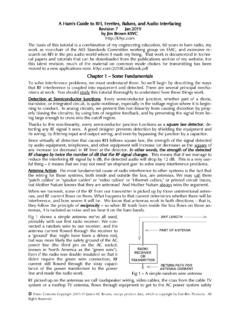
5 It s much tougher now, when the interference sources are strong RF signals from UHF cell phones and high power TV transmitters. Again, it s series inductance that makes life difficult, this time the inductance of the capacitor s wire leads. Fig 1 This is the classic RF pin 1 problem in a mic. The cable shield goes to the enclosure, but through a wire long enough to have significant inductive reactance at VHF. The drop across the inductance is coupled to the signal zero reference, where it is added to the signal.
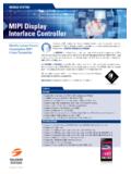
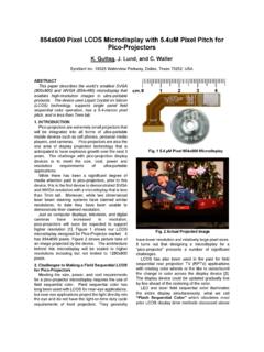
6 Fig 2 A circuit configuration that avoids a pin 1 problem. The shield goes directly to the shielding enclosure. Signal reference common also goes to the shielding enclosure, but there is no common imped-ance. Part 2by Jim BrownRandom Thoughts from ChicagoCopyright - Synergetic Audio Concepts110 Volume 31 No. 3 Summer 2003 Feed-through capacitors have been a solution to this problem since the 1930 s. They mount in a circular hole in an enclosure. One plate of the capacitor is a wire going through the enclo-sure, while the other plate is a cylinder surrounding the wire and connected to the enclosure, with a dielectric (insulation) between the plates.
7 This circu-lar construction minimizes the inductance through the capaci-tor to the chassis enclosure, while the wire coming into the chassis enclosure still has inductance. The resulting electrical circuit is an effective RF filter while it also prevents a hole in the shielding. To provide the most effective shielding, both cable shields and the shells of connectors within equipment should be bonded to the chassis. (Retired Bell Labs engineer and EMC authority Henry Ott observes that if this connection is to the outside of the enclosure, skin effect will keep RF currents outside the enclosure as well.)
8 But what about cable-mount connectors? To make the EMC engineering community happy, mic cables should tie the cable shield to the connector shell, but to make audio folks happy the shield should go only to pin 1. A few years ago, I proposed the concept of making a cylindrical connection to the shield in cable-mounted connectors much like that in a BNC connector, with that cylinder surrounded by a cylindrical dielectric that was itself surrounded by a cylindrical plate connected to the connector shell. Such construction would form a capaci-tor having very low series inductance, turning the XL connector into a two-circuit feed-through capacitor.
9 It would connect the shield to the shell at RF, while isolat-ing it from the shell at audio frequencies and DC. When used on mic cable, the shield is also soldered to pin 1. When used at line level inputs in a rack, an installer could decide not to connect the shield to pin 1, but it would still be connected to the shell at RF through the capacitor. Engineer Joanne Dow observed that if such a con-nector were to be used with a connection to pin 1, the capacitor and the series inductance to the chassis through pin 1 would form a parallel resonance, and suggested a ferrite bead surrounding pin 1 in the cable connector to lower the Q of the resonance.
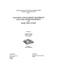
10 It took a while for these ideas to germinate, but before long, engineers at Neutrik had begun work on a practical implementation, and by early 2002 had devel-oped engineering prototypes. British consultant John Woodgate tested them in his lab, and I tested them both in my lab and in the field. The results met my expecta-tions, and yielded an unexpected bonus they solved RF pin 1 problems, even when pin 1 was connected at both ends! A simple circuit study shows why. Figure 3 shows a cable using the new connectors used with the mic shown in Fig 1 in from the last newsletter issue.