Transcription of Reference Flow Measurement - Gilson Eng
1 Moore Process Automation Solutions - Flow Measurement300 Flow MeasurementFUNDAMENTALSF lowmetering terms can often seem cryptic. Here are defi-nitions of some of the most commonly Accuracy is a quantity defining the limit that errors willnot exceed. This value should include the combined ef-fects of conformity, hysteresis, deadband, and repeatabil-ity errors. When applied to flowmeters, accuracy is specifiedin one of two different ways; % of full scale or % of OF FULL SCALEA % of full scale accuracy specification defines an expand-ing error envelope. For a flowmeter with a flow range of 0to 100 gpm and accuracy of 1%, FS will read +/-1gpmanywhere in its operating range. This corresponds to+/-1% of rate at full scale and +/-10% of rate at 10% of OF RATEA % of rate accuracy specification defines a constant errorenvelope.
2 For the previous flowmeter with the same flowrange and an accuracy of 1% of rate, the reading will be+/-1% of actual flowrate anywhere in the meters operatingrange. As a result, at full scale the reading will be +/-1 gpmand at 10 gpm it will be +/- 1 contains graphs that illustrate the difference in %of rate and % of span accuracy is the closeness of agreement between con-secutive measurements of the same flow. This can also bespecified as a % of full scale or a % of refers to the minimum and maximum mea-surable flowrates. For example, if the maximum flowrateis 100 gpm and the minimum flowrate is 10 gpm, therangeability is 10% to 100%.TURNDOWNT urndown conveys the same information as rangeabilitybut in a slightly different way. Turndown is the ratio ofmaximum flow to minimum flow.
3 For the same flowmeterwe used in the rangeability example, the turndown wouldbe 100/10 to 1 or 10 to a newtonian fluid, viscosity is the same as consistencyand is the resistance offered by the fluid to will be stated as either absolute or kinematic vis-cosity. Absolute viscosity is the fundamental viscositymeasurement of a fluid and has units of Poises in the cgssystem. Kinematic viscosity is equal to absolute viscositydivided by the fluid density and has units of Stokes in thecgs NUMBERR eynolds Number is dimensionless quantity that is pro-portional to the ratio of inertia forces to viscous forces in aflow system. The proportional constant is the characteris-tic length of the system. For Pipe Reynolds Number, thecharacteristic length is the pipe diameter.
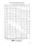
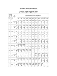
4 Reynolds Num-ber is a convenient parameter by which to compare differ-ent flow systems. Pipe Reynolds Number can be found byusing the following equations:R = [DV/v] or [DV /u]whereR = Reynolds NumberD = inside pipe diameter (ft or m)V = fluid velocity (ft/s or m/s)v= kinematic viscosity (ft2/s or stokes) = fluid density (lb/ft3 or kg/m3)u= absolute viscosity (lb/ft s or poises)Many convenient hybrid forms of the Reynolds Numberequation exist. One such equation for liquid is:R = C*Q(GPM) v(cSt)Where C is the constant from Table 1. Table 1 is valid forschedule 40, 1 Values of C for Schedule 40 PipePipe SizeC3/4"38371" "19642"15303"10314"785 For other than schedule 40, pipe C is equal to:C = 3162/pipe ID (inches)FIGURE 1 % of Rate vs. % of Span Accuracy1020304050607080901000246810-2-4 -6-8-10 Accuracy vs FlowrateError in % of RateFlowrate% Rate% Fullscale% Rate% FullscaleAccuracy vs.
5 FlowrateFlowrateError in % of rateAmericas +1 215 646 7400 ext. 6613 Asia Pacific +65 299 6051 Europe +44 1935 706262 Reference - Flow Measurement301 MassFlowratelbm/seclbm/minlbm/hrgm/secgm /minKg/ ,2201,633 VS. MASS FLOWRATEWhen measuring a flowrate, there are two fundamentaltypes of measurements; volumetric and mass flowrate is a measure of the volume of liquidflowing through the metering device. The units for thistype of flow measure indicate that it is volumetric , GPM(Gallons Per Minute). Most flowmeters measure volumeof a fluid by measuring the velocity through a known meters include orifice plates, fluidic flowmeters, andmagnetic flowmeters measure the mass of the fluid flowingthrough the meter. The units for this type of meter indicatethat it is a mass-based Measurement , #/hr.
6 The use ofmass flowmeters is limited because of the relatively highcost of the meters and application 3 Equivalents of Mass FlowrateTABLE 2 Equivalents of volumetric FlowrateVolumetricFlowrateFt3/secFt3/min Ft3/hrGPMGPHL/minFt3 ,9301,699Ft3 , a volumetric flowmeter is used in conjunction witha flow computer to calculate the mass flowrate. If the volu-metric flowrate, denoted by Q is multiplied by the densityof the fluid, the result will be the mass flowrate, denotedby = Qwhere W is the mass flowrate: is the fluid density at flowing conditionsQ is the volumetric flowrateTables 2 and 3 give the conversion factors for volumetricand mass flowrates KNOWN UNKNOWN KNOWN Reference - Flow MeasurementMoore Process Automation Solutions MASS FLOW CALCULATIONS-Liquid Flow Measurement , Linear MeterIf the mass flow is desired for a liquid, the volumetricflowrate must be multiplied by the density of the fluid.
7 Thereare basic approaches to this problem. The first and sim-plest approach is to assume the density is constant andmultiply the volumetric flowrate by this value. This ap-proach is described by the following equation:W = (const)QHowever, the density of a fluid can often vary significantlyover temperature. These variations in density will causeerrors in the calculated mass flow. To correct for densityvariations over temperature, it is common to measure boththe flowrate and temperature of the liquid. The tempera-ture is used to determine the density at flowing , the density versus temperature relationship will bestored in a characterizer block. Figure 2 shows a typicalconfiguration for computing mass flowrate for a liquid withvarying density.
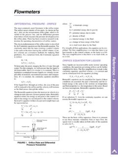
8 The following equation describes this ap-proach:W = (calc)QLIQUID FLOW Measurement - SquareLaw MeterIf the flow transmitter is an orifice plate, you can also cal-culate mass flow by taking density into account. However,if you are going to calculate the flowing density, it is bestto correct the basic orifice calculation for changes in den-sity also. The basic orifice equation for liquid is:Q = K' [ P1 - P2 ]1/2( )1/2 Multiplying this equation by density results in:W = Q = K' [ (P1 - P2) ]1/2In these equations, the quantity (P1 - P2) is the differentialpressure measured by the differential pressure performing a mass flow calculation, do not take thesquare root of the flow signal in the transmitter. Figure 3shows a typical configuration for performing mass flowcomputation on a liquid orifice FLOW Measurement -Linear Meter and Square Law MeterMass flow calculations for steam are performed in muchthe same way as for liquids.
9 The major difference betweenliquid and steam, or even matter gas flows , is that the flow-ing density of steam and gas are dependent on both tem-perature and pressure. If the steam to be metered issufficiently superheated, then it can be treated as an idealgas and the density can be calculated. Many times, how-ever, this is not the the steam cannot be treated as an ideal gas, an at-tempt must be made to characterize the density of the steamin a usable manner. One thing that helps in this situation isthat the pressure of the steam is often controlled. If thepressure is being controlled, then the density of the steamat the pressure can be characterized over the expected tem-perature range. Once this is achieved, the actual calcula-tion of mass flow is the same as it was with a 2 Mass Flow CalculationLiquid\Saturated Steam (Linear Meter)FIGURE 3 Mass Flow CalculationLiquid\Saturated Steam (Square Root Meter)ANALOGINPUTTT+26 VRTDorT/CFT+26 VANALOGINPUTMATHT emperatureMass Flowrate (W)TOTALIZER CHARAC- TERIZERD ensity (p)VolumetricFlowrate (Q)Equationw = pQDensityTemperatureANALOGINPUTTT+26 VRTDorT/CFT+26 VANALOGINPUTMATHT emperatureMass FlowrateW = [K'2p(P1-P2)]1/2 TOTALIZER CHARAC- TERIZERD ensity (p)(P1-P2)EquationSo = K'2p(P1-P2)SQUAREROOTT emperatureDensityDensity ( )Equationw = QEquationSo = K'2 (P1-P2)Mass FlowrateW = [K'2 (P1-P2)]
10 ]1/2 Reference - Flow MeasurementAmericas +1 215 646 7400 ext. 6613 Asia Pacific +65 299 6051 Europe +44 1935 706262303 GAS FLOW Measurement - LinearMeterFor gases and superheated steam, it is necessary to useboth the flowing temperature and the flowing pressure tocalculate mass flowrate. The temperature and pressure areused to calculate the density at flowing conditions. Theideal gas law is used to determine the density from thepressure and temperature. It is useful to do an exampleproblem to demonstrate the the mass flowrate of natural gas through a linearmeter given the following information:flow range0-5000 #/hroperating pressure100 psiaoperating temperature80oFFrom this information we calculate the density at normalor base conditions.