Transcription of Reference test procedure for field vane tests
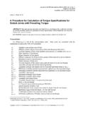
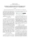
1 1 Reference TEST procedure Rev. 3 DGS field COMMITEERodFriction reducerCross-section A-ADirection ofrotationRodFriction reducerCross-section A-ADirection ofrotationReference test procedure for field vane testsDanish Geotechnical Society - field CommitteeRevision 3 August 1999(English translation September 2009 - In case of disagreement the Danish versionapplies)1. INTRODUCTIONThis Reference test procedure provides a guideline for execution of field vane tests in cohesive shear vane test determines the vane strength of the soil. Normally this indicates the undrainedshear strength of the GeneralThe vane probe consists of two blades mounted perpendicular to each other at the end of acylindrical rod. The blades have rounded corners and sharpened edges. Just above the blades a ringis inserted to reduce the friction between the rod and the penetrated the torque on the rod is measured by a spring scale or a dial indicator springconnecting a fixed arm with the handle. It is this type of equipment that is described , the measurement can be performed by a torque wrench.
2 If a torque wrench isapplied, it shall be verified that the level of accuracy and quality assurance complies with thedescription for the traditional 1. The vane probe. The figure shows a hand vane AA deep vane equipment is applied in the bottom of a borehole in connection with the execution ofa geotechnical investigation boring. The hand vane equipment has a low weight and is designedfor shallow dimensions of the blades are used for measurements in cohesive soils with differentstrengths. The connection of the blades to the rod is shown in Figure 1. The blades are welded to theconical tip of the TEST procedure Rev. 3 DGS field COMMITEEThe height of the vane is two times the diameter (however, for four times the diameter), allcorners are rounded, but the edges are sharpened. The traditionally applied vane blade dimensionsare shown in Table 1, where V signifies deep vanes and HV hand vanes. Generally, deviations ofhanddup to 2 % are 1. Geometry of the vanesVaneNoH(mm)d(mm)r(mm)t(mm)d1(mm)d2( mm) Deep vaneFour vane sizes are applied: V4, V5, and number denotes the vane diameter in torque is measured by a 50 kg dial indicator spring (dynamometer) with a moment arm (a) of300 mm (measured at excitation of the dynamometer).
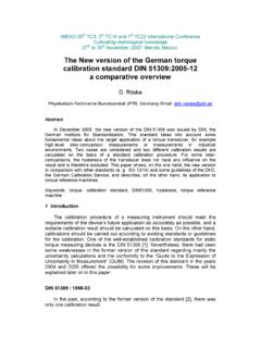
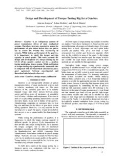
3 The equipment rod is shown in Figure equipment shall be suspended by a clutch with low friction to prevent penetration into the soilduring the test. For greater depths a ball bearing is applied to reduce the 2. The deep vane equipmentDrilling rodRoller bearing suspensionFixed armHandleDrilling rodDial indicator springClutchVane rodVaneView from aboveDrilling rodCasingBottom of boreholeDrilling rodCasingBottom of borehole3 Reference TEST procedure Rev. 3 DGS field Hand vaneTwo vane sizes are applied, HVA and HVB, with vane diameters of 33 and 48 mm, respectively (alldimensions are given in Table 1).The torque is measured by a 25 kg spring scale (an app. 250 N dynamometer). The arm (a) shallbe 175 mm at 6 kg and 162 mm at full range (25 kg). The equipment is shown in Figure 3. For testsin deep excavations the rod can be 3. The hand vane equipment3. TEST PROCEDUREB efore the execution of a vane test it shall be controlled that the vane blades are undamaged. Thevane size should be chosen with respect to the actual soil in order that the maximum value at failurewill occur in the upper 2/3 of the total range of the all tests in boreholes loose soil at the base of the hole must be removed and it shall beassured that an excess pore pressure exists in the vane shall be pressed or hammered gently into the soil without rotation, until the base of theblades is two blade heights below the base of the borehole or the soil surface.
4 However, a depth m below the base of the borehole is normally used for vane numbers V4, V5, HVA and HVB,while depths of m and m are used for vane number and , the test is carried out immediately after the vane has been turn of the handle shall be performed in a steady manner as slowly as possible. The maximumspeed of rotation should be 1 rpm (revolution per minute). The size of the vane and the measuredmaximum torque must be written in a test report together with the depth below soil surface to thebase of the each test in undisturbed soil the vane shall be given 10 revolutions and the test is less than 10 revolutions are applied this must be stated in the test report. The measured maximumtorque must also be written in the test rodHandleSpring scaleFixed armMoment armVaneVane rodHandleSpring scaleFixed armMoment arm4 Reference TEST procedure Rev. 3 DGS field COMMITEEWhen vane numbers V4 and V5 are used the procedure mentioned above (test in undisturbed andremoulded soil) may be repeated m below the first test.
5 This is called a double test. tests anddouble tests in boreholes are normally carried out per m depth. tests with vane numbers HVAand HVB are normally carried out per m the execution of the test the following incidents shall be large variation of the resistance because of stones. The observation shall be reported,but no measurement is written in the test resistance because of sand grains. The observation shall be reported and themeasurement is written in the test TEST REPORTThe results of all vane tests shall be specified in the test report. The specifications must include thefollowing number and of the below soil surface to the base of the load in undisturbed load in remoulded because of sand, gravel or INTERPRETATION OF TEST RESULTSThe vane strength of the soil shall be determined by using the equation:MagPcv Where:vcis the undrained vane strength in undisturbed soil. It may be substituted by the remouldedstrengthrvcgPis the measured force on the handle (Pis in kg and therefore multiplied byg= m/s2)ais the moment arm in mMis the static moment of the total shear surface in three components:321 MMMM 5 Reference TEST procedure Rev.
6 3 DGS field COMMITEEW here1 Mconcerns the vertical edges of the blades,2 Mconcerns the top and base of the bladesand3 Mconcerns the circular corners of the blades:)2(2121rhdM 32)2(34rdM )2(8)2(2232223rdrrrdrM avaries typically 10% (dependent on the load) for vane numbers HVA and HVB, whereas it isalmost constant for vane numbers approximately with:Pa Then the vane strength is written:221)(PKPKMPgPcv Where:MgK 1 MgK 2In Table 2 values are given for all the vane sizes mentioned previously, and the vane strength atmaximum load can be 2. Calculation of vane strength atmaximum loadVaneNo. mm mm kg]M[m3]K1[kN m-2kg-1]K2(kN m-2kg-2]Pmax[kg]cv,max[kN/m2] vane strengths at loads from zero to maximum are given in Table TEST procedure Rev. 3 DGS field COMMITEET able 3. Conversion to vane strengthP[kg]cv[kN/m2] TEST procedure Rev. 3 DGS field COMMITEE6. QUALITY ASSURANCEThe moment arm, the distance from the axis of rotation to the axis of the load cell, shall be 300mm whenP= 35 kg in tests with vane numbers Likewise it must be 175 mm and 162mm at 6 kg and 25 kg, respectively in tests with vane numbers HVA and HVB.)
7 As an alternative totable 3 the calculation ofvcmay be based directly on the measured values of the moment load cells shall be calibrated frequently. Well known weights may be used for this purpose. Adefective load cell must not be shall be controlled that the vane blades have no damages after each series of tests . Blades thatare twisted or defer from the dimensions described in section must not be tests with vane numbers it shall be assured frequently that the ball bearings installedto reduce friction are working properly. The vane should be rotated one revolution when it is justabove the base of the total inaccuracy of the equipment is expected to be within 10 % when the describedconditions are fulfilled. However, worn vane blades may increase this value.