Transcription of Reinforcing Steel - Chapter 7 - South Dakota Department of ...
1 Reinforcing Steel - Chapter 7 The What and Where of Reinforcing Steel What is Reinforcing Steel High strength Steel rods Where is Reinforcing Steel Used Placed in concrete to increase resistance to bending and tension Types of Reinforcing Steel Smooth or Plain bars Used in Spiral Steel placed in Columns Normally fabricated in spiral form before delivered to work site Types of Reinforcing Steel Deformed bars (epoxy coated or plain) Irregular surface so concrete can grip Types of Reinforcing Steel Deformed bars Types of Reinforcing Steel Deformed bars Acceptance Requirements When Steel is delivered check who is supplier Certification & Testing depends on.
2 Is Steel from Certified Fabricator is Steel from Non-Certified Fabricator Acceptance Requirements Certified Fabricator uncoated bars - shipping list/bill of lading uncoated bars - check list against list of Steel for project uncoated bars - inspect for rust, scales, proper grade markings and signs of mishandling Acceptance Requirements Non-Certified Fabricator certified copy of mill test report of chemical analysis for each lot/heat number is forwarded to Engineer visual inspection of heat number, size, length, shape & condition of shipment. Inspector signs on certified mill test . Acceptance Requirements For all Epoxy Coated bars certified copy of mill test report of chemical analysis for each lot/heat number is forwarded to Engineer visual inspection of heat number, size, length, shape & condition of shipment.
3 Inspector signs on certified mill test . A Certificate of Compliance that epoxy coating and coating process conform to specs. Check for voids, holes and cracks. Storage and Handling Take care unloading to avoid kinking and other damage Support long bars at several points Storage and Handling Do not drag on ground to prevent damage to the Reinforcing Steel or contamination of the Steel rebar Storage and Handling Do not stockpile where equipment could damage the Steel rebar Storage and Handling Lastly protect non-coated rebar to minimize rusting Storage and Handling Epoxy-Coated bars use padded/non-metallic slings to unload and move take care to prevent excess sagging during handling do not drop or drag if stored more that 30 days, cover with waterproof.
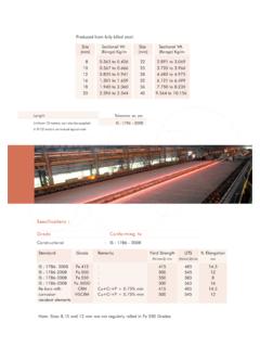
4 Opaque cover to protect from ultraviolet rays Storage and Handling Pre-Installation Check Verify size, grade, length and shapes before Steel is installed in the structure Use Reinforcing Schedule found in project plans to verify size, length and shapes Pre-Installation Check Reinforcing Schedule Pre-Installation Check Cut bars Straight bars are not detailed except when cut bars are needed Pre-Installation Check Cut bars Bar Identification Table properties of Standard Reinforcing BarsASTM Standard Reinforcing BarsNominal Dimensions Round SectionsInch-PoundBar SizeMetric BarSizeNominalWeight (kg/m)DiameterIn. (mm) (mm2)PerimeterIn.
5 (mm)#3# ( ) ( ) (71) ( )#4# ( ) ( ) (129) ( )#5# ( ) ( ) (199) ( )#6# ( ) ( ) (284) ( )#7# ( ) ( ) (387) ( )#8# ( ) ( ) (510) ( )#9# ( ) ( ) (645) ( )#10# ( ) ( ) (819) ( )#11# ( ) ( ) (1006) ( )#14# ( ) ( ) (1452) ( )#18# ( ) ( ) (2581) ( )Bar Identification Material Sources N=Billet Steel - Grade 40 or 60 (new Steel ) S=Billet Steel w/added reqs. R=Rail Steel - Grade 40 or 60 (melted down railroad track) A=Axle Steel - Grade 60 (from carbon Steel RR car axles) W=Low Alloy Steel - Grade 60 Bar Identification Grade 60 Grade 60 Grade 40,50 Inch-Pound BarsInch-Pound BarsGrade 400 Metric Bars60S11H4S36 HMain RibsLetter ofProducing MillBar SizeType SteelGrade MarkS11HS11 HGrade 300 Grade 400 Metric BarsS11HS11 HMain RibsLetter or Symbolof Producing MillBar SizeType SteelGrade LineOne Line Onlynumber system - grade markscontinuous line system - grade marksDimensions & Bends Straight bars During inspection allow + or - 1 from specified length Measure with Steel ruler If in bundle, measure several.
6 Eyeball the rest Dimensions & Bends Bent bars check details in Reinforcing schedule check each dimension & overall length measure a few, eyeball the rest if any out of tolerence, reject it and measure remainder of shipment check against Standard Hook & Stirrup Dimensions Charts Dimensions & Bends Bent bars Table Standard Hook DimensionsStandard Hook Dimensions180 Hooks(mm)90 Hooks(mm)Inch-PoundBar SizeMetric BarSizeD(mm)A or GJA or G#3#102 (125)5 (125)3 (75)6 (150)#4#133 (80)6 (150)4 (100)8 (200)#5#163 (95)7 (175)5 (125)10 (250)#6#194 (115)8 (200)6 (150)1 -0 (300)#7#225 (135)10 (250)7 (175)1 -2 (355)#8#256 (150)11 (280)8 (200)1 -4 (405)#9#299 (240)1 -3 (380)11 (300)1 -7 (480)#10#3210 (275)1 -5 (430)1 -1 (335)1 -10 (560)#11#3612 (305)1 -7 (480)1 -2 (375)2 -0 (610)#14#4318 (465)2 -3 (685)1 -9 (540)2 -7 (790)#18#5724 (635)3 -0 (915)2 -4 (725)3 -5 (1040)Dimensions & Bends Bent bars Table Stirrup DimensionsStirrup Dimensions(Tie Bends Similar)90 Bends(mm)135 Bends(mm)Inch-PoundBar SizeMetric BarSizeD(mm)A or GA or GH#3#101 (40)4 (100)4 (100)2 (65)#4#132 (50)4 (115)4 (115)3 (75)#5#162 (65)6 (150)5 (140)3 (95)#6#194 (115)1 -0 (300)
7 7 (195)4 (115)#7#225 (135)1 -2 (355)9 (230)5 (135)#8#256 (150)1 -4 (405)10 (260)6 (150)details details Placement of Reinforcing Steel Place Steel according to plans Maintain proper Clear Cover & Spacing Clear Cover - distance between finished surface of concrete and nearest surface of rebar Spacing - distance between centers of rebar Placement of Reinforcing Steel Supporting Devices Metal Chairs & Bolsters premanufactured light to heavy gauge wire support rebar from bottom of slab for epoxy coated bars use epoxy or plastic coated chairs & bolsters all plastic chairs & bolsters are not allowed Placement of Reinforcing Steel Supporting Devices Metal Chairs & Bolsters Variable minimum 4" (100mm)
8 12" (300mm)Placement of Reinforcing Steel Supporting Devices Precast Mortar Blocks used in place of chairs or bolsters have a tapered trapezoidal shape made of concrete of the same or higher strength can be precast with wire tie Placement of Resteel Wire Hangers and Ties use 16 gauge wire or larger to fasten bars where they cross for epoxy bars use coated wires Placement of Reinforcing Steel Wood used to hold reinforcement most often used to hold circular patterns for columns placed outside the poured concrete must be removed after concrete has enough strength to self support Placement of Reinforcing Steel Support devices NOT
9 Allowed Pebbles - tend to tip Broken Stone or Brick - undesirable appearance Metal Pipe - mortar doesn t flow into pipe leaving a void Embedded Wooden Blocks - wood rots - not same strength as concrete Metal Devices - if exposed they rust Placement of Reinforcing Steel Placement Methods by single piece or by section Placement of Reinforcing Steel Inspections Inspectors job is to insure correct bars are properly placed & secured Count bars ; compare to plans Check bar sizes. Substitution of bar sizes is not an option without authorization from Office of Bridge Design Check for proper tie pattern Placement of Reinforcing Steel Inspections Tie Pattern where two bars cross Greater than 12 spacing in one direction Less than 12 spacing Placement of Reinforcing Steel Inspections Tie Pattern - Bridge Deck & Box Culverts Tie top mat to lower supporting member to prevent mat from floating up during concrete pour Girder Bridges - tie every 8 feet Slab Bridges/Box Culverts - tie every 12 feet Placement of Reinforcing Steel Inspections Check Splices
10 Overlap should be wired in two places check plans for overlap LapCORRECTWire TiesINCORRECTP lacement of Reinforcing Steel Inspections Check for proper spacing of bars Verify with plan requirements reinforcement spacing should be within + or - 1/2 inch of plan location Uneven distribution of rebar can cause concrete cracking Placement of Reinforcing Steel Inspections check for proper cover proper cover helps prevent buckling under compressive loads rusting from exposure scaling of concrete surface because reinforcement is too close to surface Maintain cover within + or - 1/4 of plan specs. Placement of Reinforcing Steel Inspections results of improper cover Placement of Reinforcing Steel Inspections check beginning and end point of Steel bars verify against plans Placement of Reinforcing Steel Inspections Check Condition of bars free of dirt, oil.