Transcription of Chapter 5 Footing Design - Engineering
1 1 Chapter 5 Footing Design By S. Ali Mirza1 and William Brant2 Introduction Reinforced concrete foundations, or footings, transmit loads from a structure to the supporting soil. Footings are designed based on the nature of the loading, the properties of the Footing and the properties of the soil. Design of a Footing typically consists of the following steps: 1. Determine the requirements for the Footing , including the loading and the nature of the supported structure. 2. Select options for the Footing and determine the necessary soils parameters. This step is often completed by consulting with a Geotechnical Engineer. 3. The geometry of the foundation is selected so that any minimum requirements based on soils parameters are met. Following are typical requirements: The calculated bearing pressures need to be less than the allowable bearing pressures. Bearing pressures are the pressures that the Footing exerts on the supporting soil.
2 Bearing pressures are measured in units of force per unit area, such as pounds per square foot. The calculated settlement of the Footing , due to applied loads, needs to be less than the allowable settlement. The Footing needs to have sufficient capacity to resist sliding caused by any horizontal loads. The Footing needs to be sufficiently stable to resist overturning loads. Overturning loads are commonly caused by horizontal loads applied above the base of the Footing . Local conditions. Building code requirements. 1 Professor Emeritus of Civil Engineering , Lakehead University, Thunder Bay, ON, Canada. 2 Structural Engineer, Black & Veatch, Kansas City, KS. 2 4. Structural Design of the Footing is completed, including selection and spacing of reinforcing steel in accordance with ACI 318 and any applicable building code. During this step, the previously selected geometry may need to be revised to accommodate the strength requirements of the reinforced concrete sections.
3 Integral to the structural Design are the requirements specific to foundations, as defined in ACI 318-05 Chapter 15. Types of Foundations Shallow footings bear directly on the supporting soil. This type of foundation is used when the shallow soils can safely support the foundation loads. A deep foundation may be selected if the shallow soils cannot economically support the foundation loads. Deep foundations consist of a Footing that bears on piers or piles. The Footing above the piers or piles is typically referred to as a pile cap. The piers or piles are supported by deeper competent soils, or are supported on bedrock. It is commonly assumed that the soil immediately below the pile caps provides no direct support to the pile cap. Allowable Stress Design and Strength Design Traditionally the geometry of a Footing or a pile cap is selected using unfactored loads. The structural Design of the foundation is then completed using strength Design in accordance with ACI 318.
4 ACI Committee 336 is in the process of developing a methodology for completing the entire Footing Design using the strength Design method. Structural Design The following steps are typically followed for completing the structural Design of the Footing or pile cap, based on ACI 318-05: 1. Determine Footing plan dimensions by comparing the gross soil bearing pressure and the allowable soil bearing pressure. 2. Apply load factors in accordance with Chapter 9 of ACI 318-05. 3. Determine whether the Footing or pile cap will be considered as spanning one-way or two-ways. 4. Confirm the thickness of the Footing or pile cap by comparing the shear capacity of the concrete section to the factored shear load. ACI 318-05 Chapter 15 provides guidance on selecting the location for the critical cross-section for one-way shear. ACI 318-05 Chapter 11 provides guidance on selecting the location for the critical cross-section for two-way shear.
5 Chapter 2 of this handbook on shear Design also provides further Design information and Design aids. 35. Determine reinforcing bar requirements for the concrete section based on the flexural capacity along with the following requirements in ACI 318-05. Requirements specific to footings Temperature and shrinkage reinforcing requirements Bar spacing requirements Development and splicing requirements Seismic Design provisions Other standards of Design and construction, as required Footings Subject to Eccentric Loading Footings are often subjected to lateral loads or overturning moments, in addition to vertical loads. These types of loads are typically seismic or wind loads. Lateral loads or overturning moments result in a non-uniform soil bearing pressure under the Footing , where the soil bearing pressure is larger on one side of the Footing than the other. Non-uniform soil bearing can also be caused by a foundation pedestal not being located at the Footing center of gravity.
6 If the lateral loads and overturning moments are small in proportion to the vertical loads, then the entire bottom of the Footing is in compression and a P/A M/S type of analysis is appropriate for calculating the soil bearing pressures, where the various parameters are defined as follows: P = The total vertical load, including any applied loads along with the weight of all of the components of the foundation, and also including the weight of the soil located directly above the Footing . A = The area of the bottom of the Footing . M = The total overturning moment measured at the bottom of the Footing , including horizontal loads times the vertical distance from the load application location to the bottom of the Footing plus any overturning moments. S = The section modulus of the bottom of the Footing . If M/S exceeds P/A, then P/A - M/S results in tension, which is generally not possible at the Footing /soil interface.
7 This interface is generally only able to transmit compression, not tension. A different method of analysis is required when M/S exceeds P/A. Following are the typical steps for calculating bearing pressures for a Footing , when non-uniform bearing pressures are present. These steps are based on a Footing that is rectangular in shape when measured in plan, and assumes that the lateral loads or overturning moments are parallel to one of the principal Footing axes. These steps should be completed for as many load combinations as required to confirm compliance with applicable Design criteria. For instance, the load combination with the maximum downward vertical load often causes the maximum bearing pressure while the load combination with the minimum downward vertical load often causes the minimum stability. L 4 1. Determine the total vertical load, P. 2. Determine the lateral and overturning loads.
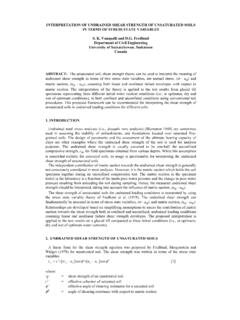
8 3. Calculate the total overturning moment M, measured at the bottom of the Footing . 4. Determine whether P/A exceeds M/S. This can be done by calculating and comparing P/A and M/S or is typically completed by calculating the eccentricity, which equals M divided by P. If e exceeds the Footing length divided by 6, then M/S exceed P/A. 5. If P/A exceeds M/S, then the maximum bearing pressure equals P/A + M/S and the minimum bearing pressure equals P/A-M/S. 6. If P/A is less than M/S, then the soil bearing pressure is as shown in Fig. 5-1. Such a soil bearing pressure distribution would normally be considered undesirable because it makes the Footing structurally ineffective. The maximum bearing pressure, shown in the figure, is calculated as follows: Maximum Bearing pressure = 2 P / [(B) (X)] Where X = 3(L/2 - e) and e = M / P Fig. 5-1 Footing under eccentric loading Footing Design Examples The Footing examples in this section illustrate the use of ACI 318-05 for some typical Footing designs as well as demonstrate the use of some Design aids included in other chapters.
9 However, these examples do not necessarily provide a complete procedure for foundation Design as they are not intended to substitute for Engineering skills or experience. 5 FOOTINGS EXAMPLE 1 - Design of a continuous (wall) Footing Determine the size and reinforcement for the continuous Footing under a 12 in. bearing wall of a 10 story building founded on soil. Given: / c = 4 ksi /y = 60 ksi Dead Load = D = 25 k/ft Live Load = L = k/ft Wind = W = 4 k/ft (axial load due to overturning under wind loading) Seismic = E = 5 k/ft (axial load due to overturning under earthquake loading) Allowable soil bearing pressures: D = 3 ksf = "a" D + L = 4 ksf = "b" D + L + (W or E) = 5 ksf = "c" Procedure Computation ACI 318-05 Section Design Aid Sizing the Footing . Ignoring the Footing self-weight; D/a = 25/3 = ft (D + L)/b = = ft controls (D + L + W)/c = = ft (D + L + E)/c = = ft Use B = 10 ft Required strength.
10 U = = (25) = 35 k/ft or ksf U = + = (25) + ( ) = 50 k/ft or ksf (Controls) U = + + = (25) + (4) + = k/ft or ksf U = + = (25) + (4) = k/ft or ksf U = + + = (25) + (5) + 6 = k/ft or ksf U = + = (25) + (5) = k/ft or ksf Design for shear. Calculate Vu at d from the face of the wall shear = Assume Vs = 0 (no shear reinforcement) cnVV = )db'f2(Vwcc = Try d = 17 in. and h = 21 in. 1000/)17)(12)(40002( = k/ft Vu = (10/2 - 6/12 - 17/12)( ) = k/ft ucnVVV>= OK Calculate moment at the face of the wall Compute flexural tension reinforcement Shrinkage and temperature reinforcement Mu = (5)( )2/2 = ft-k/ft Kn = Mu (12,000)/(bd2) Kn = (12,000)/[(12)(17)2] = 176 psi For Kn = 176 psi, select = As = bd = (12) (17) = in2/ft Check for As,min= bh As,min= (12)(21)= in2/ft < OK Use bottom bars #8 @ 13 in c/c hooked at ends.