Transcription of CHAPTER 4. Reinforced Concrete - assakkaf
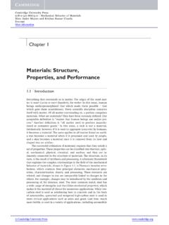
1 1 Fifth EditionReinforced Concrete Design A. J. Clark School of Engineering Department of Civil and Environmental EngineeringCHAPTER4 Reinforced CONCRETEA Fundamental Approach-Fifth EditionREINFORCED CONCRETEENCE 454 Design of Concrete StructuresDepartment of Civil and Environmental EngineeringUniversity of Maryland, College ParkSPRING 2004By Dr . Ibrahim. AssakkafCHAPTER 4. Reinforced CONCRETES lide No. 1 ENCE 454 AssakkafIntroduction Concrete is weak in tension but strong in compression. Therefore, reinforcement is needed to resist the tensile stresses resulting from the applied loads. Additional reinforcement sometimes added to the compression zone to reduce long-term 4. Reinforced CONCRETES lide No. 2 ENCE 454 AssakkafTypes and properties of steel Reinforcement steel reinforcement consists of bars Wires Welded wire fabric The most important properties of steel are: Young s Modulus (Modulus of Elasticity), E Yield Strength, fy Ultimate Strength, fu steel Grade Designation.
2 Size or Diameter of the bar or 4. Reinforced CONCRETES lide No. 3 ENCE 454 assakkaf steel is a high-cost material compared with Concrete . It follows that the two materials are best used in combination if the Concrete is made to resist the compressive stresses and the steel the tensile stresses. Concrete cannot withstand very much tensile stress without and properties of steel Reinforcement3 CHAPTER 4. Reinforced CONCRETES lide No. 4 ENCE 454 assakkaf (a)(b)(c)Figure - xn As C Reinforced Concrete and properties of steel ReinforcementCHAPTER 4. Reinforced CONCRETES lide No. 5 ENCE 454 assakkaf It follows that tensile reinforcement must be embedded in the Concrete to overcome the deficiency. Forms of steel Reinforcement steel reinforcing bars Welded wire fabric composed of steel wire. Structural steel Shapes steel and properties of steel Reinforcement4 CHAPTER 4. Reinforced CONCRETES lide No. 6 ENCE 454 AssakkafTypes and properties of steel ReinforcementDeformed BarCHAPTER 4.
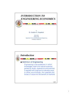
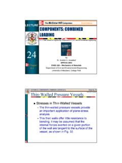
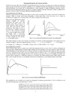
3 Reinforced CONCRETES lide No. 7 ENCE 454 assakkaf Bond between Concrete and steel To increase the bond, projections called deformationsare rolled on the bar surface as shown in Fig. 1. reinforcing bars (rebars) The specifications for steel reinforcement published by the American Society for Testing and Materials(ASTM) are generally accepted for steel used in Reinforced Concrete construction in the United States and are identified in the ACI and properties of steel Reinforcement5 CHAPTER 4. Reinforced CONCRETES lide No. 8 ENCE 454 assakkaf Yield Stress for steel Probably the most useful property of Reinforced Concrete design calculations is the yield stress for steel , fy. A typical stress-strain diagram for reinforcing steel is shown in Fig. 2a. An idealized stress-strain diagram for reinforcing steel is shown in Fig. and properties of steel ReinforcementCHAPTER 4. Reinforced CONCRETES lide No. 9 ENCE 454 AssakkafTypes and properties of steel ReinforcementStrainStressFyElasticregion yFigure 2.
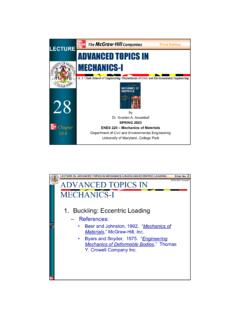
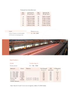
4 Typical Stress-Strain Curve for steel (b) IdealizedStrainStressFyElasticregion y(a) As Determined by Tensile TestStrainStressSlope==E6 CHAPTER 4. Reinforced CONCRETES lide No. 10 ENCE 454 AssakkafFigure 3. Typical Stress-Strain Diagrams for Various SteelTypes and properties of steel ReinforcementCHAPTER 4. Reinforced CONCRETES lide No. 11 ENCE 454 assakkaf Modulus of Elasticity or Young s Modulus for steel The modulus of elasticity for reinforcing steel varies over small range, and has been adopted by the ACI Code asTypes and properties of steel ReinforcementMPa 10200 ksi 29,000 psi 000,000,296 ===E7 CHAPTER 4. Reinforced CONCRETES lide No. 12 ENCE 454 assakkaf steel Grades and Strengths Table 1 gives reinforcement-grade strengths. Geometrical properties Table 2 provides various sizes of bars in US Customary units, while Table 3 gives the sizes in Metric and properties of steel ReinforcementCHAPTER 4. Reinforced CONCRETES lide No. 13 ENCE 454 AssakkafTable 1. Reinforced Grades and StrengthsTypes and properties of steel Reinforcement85,00075,000, 70,00070,00065,000, 56,000 Smooth wireReinforcedFabric85,00080,00075,00070 ,000 Deformed wireReinforcedFabric80,00060,000 Low-carbon steel (A706) Grade 6070,00090,00040,00060,000 Axial steel (A617)Grade 40 Grade 6070,00090,00040,00060,000 Billet steel (A615)Grade 40 Grade 60 Ultimate Strength, fu(psi)Minimum Yield Point or Yield Strength, fy(psi)1982 Standard Type8 CHAPTER 4.
5 Reinforced CONCRETES lide No. 14 ENCE 454 AssakkafTypes and properties of steel ReinforcementTable 2. ASTM Standard - English ReinforcingBarsBar Designation Diameter in Area in2 Weight lb/ft #3 [#10] #4 [#13] #5 [#16] #6 [#19] #7 [#22] #8 [#25] #9 [#29] #10 [#32] #11 [#36] #14 [#43] #18 [#57] Note: Metric designations are in bracketsCHAPTER 4. Reinforced CONCRETES lide No. 15 ENCE 454 AssakkafTypes and properties of steel ReinforcementTable 3. ASTM Standard - Metric ReinforcingBarsNote: Metric designations are in brackets Bar Designation Diameter mm Area mm2 Mass kg/m #10 [#3] 71 #13 [#4] 129 #16 [#5] 199 #19 [#6] 284 #22 [#7] 387 #25 [#8] 510 #29 [#9] 645 #32 [#10] 819 #36 [#11] 1006 #43 [#14] 1452 #57 [#18] 2581 9 CHAPTER 4. Reinforced CONCRETES lide No. 16 ENCE 454 AssakkafTypes and properties of steel Reinforcement reinforcing bars (rebars) These bars are readily available in straight length of 60 ft.
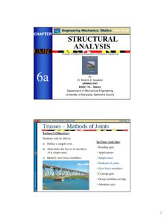
6 The bars vary in designation from With additional bars :No. 3 through No. 11No. 14 and No. 18 CHAPTER 4. Reinforced CONCRETES lide No. 17 ENCE 454 AssakkafBar Spacing and Concrete Cover for steel Reinforcement It is necessary to guard against honeycombing and ensure that the wet Concrete mix passes through the reinforcing steel without separation. Usually aggregate size in structural Concrete contains -in (19 mm) diameter coarse aggregate. Therefore, minimum allowable bar spacing and minimum required cover are 4. Reinforced CONCRETES lide No. 18 ENCE 454 assakkaf Also, to protect the reinforcement steel from corrosion and loss of strength in cases of fire, the ACI Code 318 required minimum Concrete cover: Clear distance between parallel bars in layers must not be less than bar diameter dbor 1 in. ( mm). Clear distance between longitudinal bars in columns must not be less than in. Minimum clear cover in cast-in-place Concrete beams and columns should not be less than in ( mm) when there is no exposure to weather or contact with Spacing and Concrete Cover for steel ReinforcementCHAPTER 4.
7 Reinforced CONCRETES lide No. 19 ENCE 454 assakkaf Bar Spacing12 #9bars12 #9barsBar Spacing and Concrete Cover for steel ReinforcementSpacingClear Cover11 CHAPTER 4. Reinforced CONCRETES lide No. 20 ENCE 454 AssakkafConcrete Structural Systems Floor Slabs Beams Columns Walls FoundationsCHAPTER 4. Reinforced CONCRETES lide No. 21 ENCE 454 AssakkafReliability and Structural Safety of Concrete Components Reliability The reliability of an engineering system can be defined as the system s ability to fulfill its design functions for a specified period of time. In the context of this course, it refers to the estimated percentage of times that the strength of a member will equal or exceed the maximum loading applied to that member during its estimated life (say 25 years).12 CHAPTER 4. Reinforced CONCRETES lide No. 22 ENCE 454 assakkaf Reliability Motivation Assume that a designer states that his or her designs are percent reliable (this is usually the case obtained with most LRFD design).
8 If we consider the designs of 1000 structures, this does not mean that 4 of the 1000 structures will fall flat on the ground, but rather it means that those structures at some time will be loaded into the plastic range and perhaps the strain hardening range. So excessive deformation and slight damage might occur, but not a complete and Structural Safety of Concrete ComponentsCHAPTER 4. Reinforced CONCRETES lide No. 23 ENCE 454 assakkaf Load and Resistance Factor Design (LRFD) Specifications In the previous example, it would be desirable to have 100% reliability. However, this is an impossible goal statistically. There will always be a chance of failure (unreliability), say 2 or 3 %. The goal of the LRFD Specification was to keep this to very small and consistent and Structural Safety of Concrete Components13 CHAPTER 4. Reinforced CONCRETES lide No. 24 ENCE 454 assakkaf Load and Resistance Factor Design (LRFD) Specifications To do this, the resistance or strength Rof each member of Concrete structure as well as the maximum loading W, expected during the life of the structure, are computed.
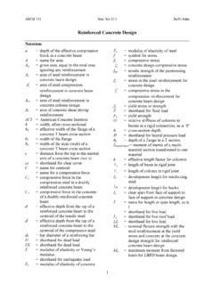
9 A structure then is s said to be safe ifWR (1)Reliability and Structural Safety of Concrete ComponentsCHAPTER 4. Reinforced CONCRETES lide No. 25 ENCE 454 assakkaf LRFD Specifications The basic criterion for strength design may be expressed as All members and all sections of members must be proportioned to meet this criterion. Eq. 1 can be thought of as a supply and a and Structural Safety of Concrete ComponentsStrength furnished Strength required(2)14 CHAPTER 4. Reinforced CONCRETES lide No. 26 ENCE 454 assakkaf LRFD Specifications The supply is considered as the strength furnished, while the demand as the strength required. The required strength may be expressed in the forms of design loads or their related moments, shears, and forces. Design loads may be defined as service loads multiplied by their appropriate and Structural Safety of Concrete ComponentsCHAPTER 4. Reinforced CONCRETES lide No. 27 ENCE 454 AssakkafReliability and Structural Safety of Concrete Components LRFD Specifications General Form = miniinWR1 Where = strength reduction factor i = load factor for the ithload component out of ncomponentsRn= nominal or design strength (stress, moment, force, etc.)
10 Wni= nominal (or design) value for the ithload component out of mcomponents(3)15 CHAPTER 4. Reinforced CONCRETES lide No. 28 ENCE 454 assakkaf LRFD Specifications Eq. 3 is the basis for Load and Resistance Factor Design (LRFD) for Concrete structural members. This equation uses different partial safety factors for the strength and the load effects. The load factors are usually amplifying factors (>1), while the strength factors are called reduction factors (<1).Reliability and Structural Safety of Concrete ComponentsCHAPTER 4. Reinforced CONCRETES lide No. 29 ENCE 454 AssakkafReliability and Structural Safety of Concrete Components Probability Based-design Approach Versus Deterministic Approach According to ASD, one factor of safety (FS) is used that accounts for the entire uncertainty in loads and strength. According to LRFD (probability-based), different partial safety factors for the different load and strength types are FS1 = mininWRLRFD 1 = miniinWR 16 CHAPTER 4.