Transcription of Review of III-V Based High Electron Mobility Transistors
1 IOSR Journal of Engineering (IOSRJEN) ISSN (e): 2250-3021, ISSN (p): 2278-8719 Vol. 05, Issue 04 (April. 2015), ||V2|| PP 13-17 International organization of Scientific Research 13 | P a g e Review of III-V Based high Electron Mobility Transistors Jun Zhu Department of ECE The University of British Columbia Abstract: - In this paper we give a Review of the high Electron Mobility transistor (HEMT). Limitation of the Silicon counterpart (MOSFET) and III-V predecessor (MESFET) are put forth as the motivations for the HEMT. Its basic working principles are presented using the AlGaAs/GaAs material system. A brief literature Review of the early development of the device is given. More recent developments in the GaN material system and the MOSHEMT structure are also examined.
2 Keywords: - high Electron Mobility transistor , two dimensional Electron gas, modulation doping, triangular quantum well I. A QUEST FOR high Mobility Mobility is defined as the velocity of charge carrier per unit strength of electric field: = [ 2 ] For devices such as the field effect transistor (FET), where the current conduction is dominated by drift of the majority carrier, it is an essential parameter limiting the transconductance: gm= dIDS sat dVGS where L refers to the channel length of the FET structure. This is a measure of variation in the channel current per gate bias change. With less charge transport to the gate electrode to achieve a fixed change in the channel current, high transconductance allows fast switching and large signal to noise ratio, making it an important figure of merit in high frequency FET applications.
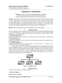
3 Therefore, carrier Mobility is the target for extensive engineering efforts. In Si, Electron Mobility of 1500 cm2/Vs is a typical value at low doping level. To improve this, III-V compounds (GaAs in particular) are used for their higher intrinsic Mobility in MESFET [1]. However, the absence of a native oxide on III-Vs sacrificestheir advantages over Si MOSFET. The doping dependence of the carrier Mobility remains an issue with III-V substitution. Unlike the oxidation problem, this was fundamental to semiconductor crystal lattices. :Mobilityversustemperatureina GaAssample with dependenceofeachscattering phenomenon. As shown in Fig. 1, the limiting scattering event around 300 K is ionized impurity (dopant) scattering, decreasing the Mobility exponentially toward lower temperatures. The next scattering event, piezoelectric, allows for order of magnitude higher Mobility [2].
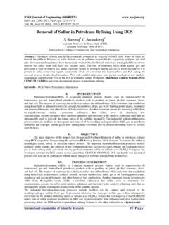
4 Hence a way to eliminate ionized impurity scattering will greatly improve device performances. Review of III-V Based high Electron Mobility Transistors International organization of Scientific Research 14 | P a g e II. THE HEMT Like many other revolutionary innovations, the solution to the Mobility problem is very intuitive: spatially separating the electrons from their parent donors. This gave rise to the high Electron Mobility transistor (HEMT). In this section, we introduce the operating principles of this device. Fig. 2: Cross-sectionalviewofthe HEMT structure[3]. Above is a typical structure of the HEMT. Directly below the gate is a heavily doped AlGaAs layer. This layer houses parent donors for the conduction Electron . A spacer layer of thin undopedAlGaAs sits between the donor layer and the undopedGaAs channel.
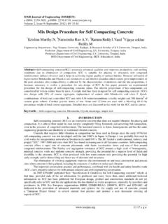
5 Device operation can be thought of, in the simplest manner, as pushing electrons from the doped layer into the undoped channel, where electrons conduct current under a horizontal electric field but are unhindered by scattering with ionized impurities, which are left in the barrier layer (AlGaAs layer). This is summarized in the band diagram below [4]. :Banddiagramoftheheterojunctionof theHEMT. The left figure shows depletion mode and the right figure shows enhancement mode. At the conduction band interface of the AlGaAs/GaAs structure, a spike barrier and triangular well is formed, typical of type-I band alignments. Electrons escape the doped layer and are trapped inside the triangular well on the undoped side, forming a pseudo two dimensional Electron gas (2 DEG) and leaving behind a depletion region on the doped side.
6 This structure allows control of accumulation via gate voltage. By engineering the conduction band discontinuity and the relative position of the Fermi level to the triangular well ground state, enhancement mode and depletion mode devices are possible. Not only does the 2 DEG suffer less ionized impurity scattering, the depletion layer serves as an insulator between the gate and the conduction channel. high Mobility and the advantages of the MOSFET are combined. In a more thorough consideration, Coulomb interaction between the 2 DEG and the ionized donors in the AlGaAs layer must be included. This is more pronounced and limits carrier Mobility at high barrier layer doping. The solution is again intuitive, since the Coulomb interaction falls off as the square of the distance, introducing an undoped spacer layer will significantly reduce the strength of this interaction.
7 Other scattering events relevant to the HEMT heterojunction include interface roughness scattering which presented a challenge to growth techniques in the early stages of the HEMT. This has been overcome with advancements in MBE systems [5]. When electrons occupy the excited states of the triangular well, scattering is more likely due to a wider distribution of Electron momentum. A simple estimation gives the DoS of the triangular well. Review of III-V Based high Electron Mobility Transistors International organization of Scientific Research 15 | P a g e 2 = 2 1013/ 2 The ground state of the triangular well can be approximated as: 0= 23 10 12 23 For typical values of sheet carrier density of ~1011/cm2, the triangular well ground state evaluates to 0 . Therefore the ground and first excited state spacing is 01 0.
8 At the heterojunction, the ground state of the triangular well supports the following number of states: 01 109/ 2 We see that the ground state of the triangular well is saturated by a typical sheet carrier density. In real device performance, the first few energy levels of the triangular well are occupied, and inter-subband scattering is a pronounced effect that limits the Mobility . Electron Mobility can be engineered to extreme values by reducing these scattering events. Having a very thick spacer layer will eliminate Coulomb interaction and limit the sheet carrier density. In 1982, the 107 2/ mark in Electron Mobility was broken [6]. In 2007, the record value is 107 2/ , and predictions exist on how to exceed 100 million [7]. These are impressive engineering and fostered the studied of some fundamental physics.
9 The quest for high Mobility is certainly successful. However, for real device applications, high Mobility is not the only goal. A large sheet charge density of the 2 DEG is required for low channel resistance and high current capacity. Therefore a compromise is made between Mobility and . Typical values for the spacer layer thickness are 25~30 . A high sheet charge density can also be achieved through increasing the doping level of the AlGaAs layer. However, when using Si as the dopant, DX centers are formed in the AlGaAs depending on the Al composition. This degrades device performance and place constraints on band gap engineering at the heterojunction. A large doping level is also disadvantageous in that excess charges left in the AlGaAs layer form parallel conduction channels and degrades device reliability.
10 To solve these problems, the delta-doping profile is applied [8]. To summarize, large conduction band discontinuity, high intrinsic material Mobility and moderate sheet charge density are ideal for HEMT operation. In the next section we give a historical account of the invention of the HEMT structure and early developments. III. HISTORY OF DEVELOPMENT The invention of the HEMT is often credited to Takashi Mimura at Fujistu but the work on modulation doped heterostructure by Raymond Dingle and company at Bell Lab were equally important [6]. While studying the optical and electrical properties of Multiple Quantum Wells (MQW) of the AlGaAs/GaAs material system, Dingle and Stormer came across the idea of modulation doping to reduce ionized impurity scattering. By placing dopants in the middle of the AlGaAs layer, unprecedented mobilities were observed in the heterostructure [9].