Transcription of Revision History - Eorex
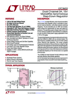
1 1EP3003 Revision History Revision (Apr. 2006) - First release. Revision (Feb. 2008).. - Modify ordering infomation.(page 2) Revision (Apr. 2008).. - Update currently version not supported burst mode information. - Modify Typical Performance Characteristics without burst mode (page 5) 2EP3003 2-CH, 600mA synchronous step - down Converter DESCRIPTION The EP3003 is a dual channel , constant frequency, slope compensated current mode PWM step - down converter. The EP3003 can supply 600mA of load current from a to input voltage. Each output voltage is adjustable from to 5V. It is ideal for powering portable equipment that runs from a single cell lithium-Ion (Li+) battery.
2 Internal synchronous , 1A power switches provide high efficiency without the need for external Schottky diodes. The EP3003 can also run at 100% duty cycle for low dropout operation, extending battery life in portable system. Pulse Skipping Mode operation at light loads provides very low output ripple voltage for noise sensitive applications. APPLICATIONS Cellular and Smart Phones Microprocessors and DSP Core Supplies Wireless and DSL Modems PDAs Portable Instruments / Media Players Digital Cameras PC Cards FEATURES High Efficiency: Up to 96% Constant Switching Frequency 600mA Output Current Integrated Main Switch and synchronous Rectifier High Switch Current: 1A on Each channel to Input Voltage Range Output Voltage as Low as 100% Duty Cycle in Dropout Low Quiescent Current: 50 A Slope Compensated Current Mode Co ntrol for Excellent Line and Load Transient Response Can be synchronized to an external oscillator Short Circuit Protection Power-on Reset Output Thermal Fault Protection <1uA Shutdown Current Small Thermally Enhanced 10-Pin MSOP and 3mm 3mm DFN Packages Typical Application Figure 1.
3 Basic Application Circuit for and Output Voltages 3EP3003 Package/Order Information MSOP: DFN: Ordering Information Absolute Maximum Rating (Note1) Input Supply .. to +6V RUN, VFB Voltages .. to VIN+ SW to VIN+ MODE/SYNC to VIN+ /POR .. to +6V P- channel Switch Source Current (DC)..800mA N- channel Switch Sink Current (DC)..800mA Operating Temperature -40 C to +85 C Junction +125 C Storage Temperature Range (MSOP) -65 C to +150 C Storage Temperature Range (DFN) .. -65 C to +125 C Lead Temperature (Soldering, 10s) ..+300 C Note 1. Absolute Maximum Ratings are those values beyond which the life of a device may be impaired. 4EP3003 Electrical Characteristics (Note 2) : (VIN =VRUN= , TA = 25 C, unless otherwise noted.)
4 Parameter Conditions MINTYP MAX unit Input Voltage Range V Input DC Supply Current Active Mode Shutdown Mode VFB= RUN=0V, VIN= , MODE/SYNC=0V 600 800 A A TA = +25 C V TA= 0 C TA 85 C V Regulated Feedback Voltage TA= -40 C TA 85 C V VFB Input Bias Current 30 nA Reference Voltage Line Regulation VIN = to %/V Threshold: VFBX Ramping Up, MODE/SYNC = 0V VFBX Ramping down , MODE/SYNC = 0V % % Power-On Reset On-Resistance 100 200 Power-On Reset (POR) Power-On Reset Delay 270K CyclesOutput Voltage Load Regulation % Peak Inductor Current VIN=3V.
5 VFB= Duty Cycle < 35% A Oscillator Frequency VFBX = MHz Synchronization Frequency MHz RDS(ON) Top Switch On-Resistance Bottom Switch On-Resistance SW Leakage VRUN = 0V, VFBX= 0V, VIN = 5V 1 A RUN Threshold -40 C TA 85 C V RUN Leakage Current 1 A Note 2. 100% production test at +25 C. Specifications over the temperature range are guaranteed by design and characterization.
6 5EP3003 Typical Performance Characteristics (TBD) 6EP3003 Functional Block Diagram EP3003 Pin Description PIN NAME FUNCTION 1 VFB1 Output Voltage Feedback Pin. An internal resistive divider divides the output voltage down for comparison to the internal reference voltage. Nominal voltage for this pin is 2 RUN1 Regulator 1 Enable control input. Forcing this pin to VIN enables regulator 1, while forcing it to GND causes regulator 1 to shut down . In shutdown, all functions are disabled drawing <1 A supply current. Do not leave RUN floating. 3 VIN Main Power Supply. Must be closely decoupled to GND with a ceramic capacitor. 4 SW1 Regulator 1 Power Switch Output.
7 Switch Node Connection to the Inductor. This pin swings from VIN to GND. 5 GND Ground 6 Mode/Sync Combination of Mode Selection and Oscillator Synchronization. This pin controls the operation of the device. When tied to VIN or GND, Burst Mode operation or pulse skipping mode is selected, respectively. Do not float this pin. The oscillation frequency can be synchronized to an external oscillator applied to this pin and pulse skipping mode is automatically selected. ( Current version Burst Mode is not supported ) 7 SW2 Regulator 2 Power Switch Output. Switch Node Connection to the Inductor. This pin swings from VIN to GND. 8 /POR Power-On Reset. This common-drain logic output is pulled to GND when the output voltage is not within of regulation and goes high after 175ms when both channels are within regulation.
8 9 RUN2 Regulator 2 Enable control input. Forcing this pin to VIN enables regulator 2, while forcing it to GND causes regulator 2 to shut down . 10 VFB2 Output Voltage Feedback Pin for Regulator 2. See VFB1 section. 11 Power Ground Connect to the ( ) terminal of COUT, and ( ) terminal of CIN. Must be soldered to electrical ground on PCB. 7 EP3003 OPERATION The EP3003 uses current mode architecture with frequency set at and can be synchronized to an external oscillator. Both channels share the same clock and run in-phase. To suit a variety of applications, the selectable Mode pin allows the user to trade-off noise for efficiency. Output voltage is set by an external divider returned to the VFB pins. An error amplifier compares the divided output voltage with a reference voltage of and adjusts the peak inductor current accordingly.
9 Over voltage and under voltage comparators will pull the POR output low if the output voltage is not within The POR output will go high after 270K clock cycles of achieving regulation. During normal operation, the top power switch (P- channel MOSFET) is turned on at the beginning of a clock cycle when the VFB voltage is below the reference voltage. The current into the inductor and the load increases until the current limit is reached. The switch turns off and energy stored in the inductor flows through the bottom switch (N- channel MOSFET) into the load until the next clock cycle. The peak inductor current is controlled by the internally compensated ITH voltage, which is the output of the error amplifier. This amplifier compares the VFB pin to the reference. When the load current increases, the VFB voltage decreases slightly below the reference.
10 This decrease causes the error amplifier to increase the ITH voltage until the average inductor current matches the new load current. The main control loop is shut down by pulling the RUN pin to ground. Low Current Control Pulse skipping mode is available to control the operation of the EP3003 at low currents. For lower ripple noise at low currents, the pulse skipping mode can be used. In this mode, the EP3003 continues to switch at a constant frequency down to very low currents, where it will begin skipping pulses. 8 EP3003 Dropout Operation The EP3003 allows the main switch to remain on for more than one switching cycle and increases the duty cycle until it reaches 100%. The output voltage then is the input voltage minus the voltage drop across the main switch and the inductor.