Transcription of RF and Digital Signals over Fiber optic cable
1 Fibre optic Products Brochure. Precision Test Systems Ltd 2013 RF and Digital Signals over Fiber optic cable Key Features Frequency range from DC to 4 GHz signal loss less than dB per 1000 m. Operates over distances of up to 50 km. Immune to EMI and RFI due to Fiber being a non-conductive medium. Security against signal interception Simple Installation Typical Applications Antenna remoting such as GPS Antennas Satcom ground stations GPS Timing Distribution including 1 pps Communication links from DC to 4 GHz Broadcast VHF/UHF links Military Communications General Description RF over optical fibre is small in size, flexible, very low loss technology using intensity modulation to transmit RF Signals .
2 The continued fall in the cost of electro-optical conversion over recent years has led to RF over Fibre being increasingly adopted for applications such as linking satellite teleports to control rooms, live outside broadcast TV, and enhancing coverage of wireless technologies such as GPS, GSM, WiMax, Tetra and P25 for example by linking remote antennas inside buildings, tunnels and mines. Typical System A typical system will consist of three main elements: Optical Transmitter, Fibre optic cable Optical Receiver (to convert back to RF). The system is defined in terms of normal RF parameters, gain, noise figure, linearity etc., and can be treated as an RF black box by a systems designer.
3 These systems use intensity modulation, which is amplitude modulation in the optical domain. The RF signal applied by the user to the optical transmitter directly modulates the intensity of a light source ( a laser diode). Fibre optic Products Brochure. Precision Test Systems Ltd 2013 No frequency conversion or analog-to- Digital conversion is involved. This technique results in the widest possible frequency response and highest possible dynamic range. At the optical receiver, the modulated light is converted back into an RF signal using a high frequency photodiode. Intensity modulation places very demanding requirements on all components in the optical path - particularly the laser diode.
4 In our products, these components have been designed for optimum efficiency, noise and linearity performance. GPS Antenna Example Our range of GPS frequency standards use a small GPS antenna that must be placed on the roof of the building to get a good view of the sky. Normally this connection is made using high quality RF coaxial cable . But because the GPS frequency is GHz, the cable can be expensive and have a large diameter for long runs. An alternative way is for us to mount an optically receiver inside out unit and an optical transmitter near the antenna. The GPS antenna is connected to the optical transmitter. The optical transmitter converts the RF GPS signal to an optical signal .
5 The optical signal is sent over a thin flexible Fiber optic cable to the optical receiver. The optical receiver converts the optical signal back to the RF GPS signal . A power supply that powers the optical transmitter can also power the GPS antenna via a voltage on the inner connector of the GPS antenna cable . Below is a picture showing this system. Different Models We can supply many models operating from DC to over 4 GHz and for various applications. The table below shows brief specifications on systems that can be supplied. However, its best to contact us directly to discuss your specific applications, so that we can direct you to the correct product.
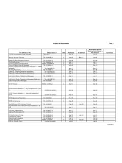
6 Fibre optic Products Brochure. Precision Test Systems Ltd 2013 RF and Optical Performance Characteristics Parameter Low Frequency Link High Frequency Link GPS Antenna Link Wideband Link Digital Data Frequency / Data Range 10kHz - 50 MHz 10-1000 MHz L1 and L2 2 kHz GHz Asynchronous NRZ, DC-10 Mbps for RS422/485, DC-460kbps for RS232/TTL RF Link Gain (nominal) 0 dB (-25dB Tx and +25dB Rx) 0 dB 0 dB 0 dB Flatness (max) (max) (max) (max) Gain Stability over operating temp range @24hrs over operating temp range @24hrs over operating temp range @24hrs Impedance / VSWR 50 / 1 : 50 / 2 : 50 /2 : 50 / 2 : 120 CNR 60dB Nominal Input signal 0dBm Nominal Output signal 0dBm Noise Figure 37dB 22 dB < 18 dB 21 dB Input P1dB +13dBm +1 dBm -10 dBm 0 dBm Maximum Input Power (without damage) +25dBm +15 dBm Output IP3 +15dBm +13 dBm SFDR 108dB Hz External LNA Voltage Capability for +5V or +12V feed from RF input of Tx Capability for +5V or +12V feed from RF input of Tx Laser Type DFB DFB Optical Wavelength 1310 nm 20 nm (1550nm/CWDM options) 1310 nm 20 nm (1550nm/CWDM options) 1310 nm 20 nm (1550nm/CWDM options) 1310 nm 20 nm (1550nm/CWDM options) 1310 nm 20 nm (1550nm/CWDM options)
7 Optical Power Output dBm (nominal) (3mW) dBm (nominal) (3mW) dBm (nominal) (3mW) Optical Connector FC/APC (E2000 and SC options) FC/APC (E2000 and SC options) FC/APC (E2000 and SC options) FC/APC Fibre cable Single mode 9/125, Corning SMF28 or equivalent United Kingdom South Africa USA Precision Test Systems LTD The Studio, Whitehouse Farm New Hall Lane, Mundon Maldon Essex, CM9 6PJ, UK Tel: +44 (0) 870 368 9608 Fax: +44 (0) 1245 330030 Email: Web: Precision Test Systems cc Randburg Gauteng Fax: 08651 58198 Email: Web: Precision Test Systems Suite # 981 14781 Memorial Dr. Houston, TX 77079 Tel: 1 888 876 4804 Fax: 1 832 201 6564 Email: Web: Full specifications available from Specifications and features subject to change without notice 091013)