Transcription of RL INNOVATOR II - Hussmann
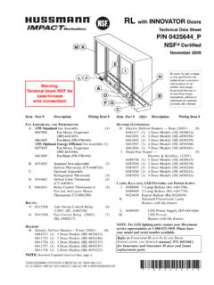
1 RL with INNOVATOR IINo Heat DoorsTechnical Data SheetP/N 0440999_QNSF Certifi edApril 2017 Warning: Terminal block NOT for case-to-case wire connection!Item Part # Description Wiring Item #FAN ASSEMBLIES, AND THERMOSTATS A. 12W Standard Energy Efficient Fan Assembly (1) 0477655 Fan Motor, Evaporator ( ) 0461805 Fan Blade ( ) B. 0474033 Standard Non-adjustable (2) Defrost Thermostat ( ) C. Optional Adjustable Refrigeration Thermostat (3) D.
2 0344662 Defrost Limit Thermostat (4) ( ) E. 0461814 Relay Control Thermostat or (5) Fan and Anti-sweat Heater Thermostat ( )(KG Only)RELAYS F. 0342598 Anti-Sweat Control Relay (6) (120V) ( ) G. 0342599 Fan Control Relay (208V) (7) ( )Item Part # (Qty.) Description Wiring Item #HEATERS H. Electric Defrost Heaters Front (208V) (8) 3015372 (1) 2 Door Models ( ) 3015373 (1) 3 Door Models ( ) 3015374 (1) 4 Door Models ( ) 3015375 (1) 5 Door Models ( ) Electric Defrost Heaters Rear (208V) (8) 3015376 (1) 2 Door Models ( ) 3015377 (1) 3 Door Models ( ) 3015378 (1) 4 Door Models ( ) 3015379 (1) 5 Door Models ( ) I.
3 Drain Pan Heater (Electric & KoolGas) (9) (120V) 0387036 (1) 2 Door Models ( ) 0387037 (1) 3 Door Models ( ) 0387038 (1) 4 Door Models ( ) 0387039 (1) 5 Door Models ( )LAMPS, BALLASTS, LED FIXTURES AND POWER SUPPLY J. 0430330 2 Lamp Ballast ( ) 0454319 3 Lamp Ballast ( ) 0424649 Export Ballast ( ) K. Standard Fluorescent Lamp Replace with like fixtures L. 0499399 LED Power Supply( ) M. LED Fixture Replace with like fixturesWe reserve the right to change or revise specifications and product design in connection with any feature of our products.
4 Such changes do not entitle the buyer to corresponding changes, improvements, additions or replacements for equipment previously sold or to INNOVATOR REACH-IN GLASS DOOR INSTALLATION AND SERVICE manual, P/N 0425683, for INNOVATOR II door and frame replacement P/N 0553987 2017 Hussmann CORPORATION BRIDGETON, MO 63044-2483 & CANADA 1-800-922-1919 MEXICO 1-800-890-2900 : Revision Q: April 2017. Updated LED energy values. Other changes marked with a bar, circle or sheet-Reach-in RLRL with INNOVATOR II Doors Technical Data Sheet2 of 7 Hussmann & CANADA 1-800-922-1919 MEXICO 1-800-890-2900 1 Dr 2 Dr 3 Dr 4 Dr 5 DrGeneral (A) Case Length (without ends or partitions) 31 1/2 (800) 62 (1575) 92 1/2 (2350) 122 7/8 (3121) 153 3/8 (3896)**NOTE: Each solid end adds approximately 2 3/8 in (60 mm) to length of line up.
5 Each partition add approximately 2 3/4 in (70 mm); case to case joints can add approximately 1/8 in (3 mm) for gasket material. Maximum O/S dimension of case back to front 43 3/4 (1111) 43 3/4 (1111) 43 3/4 (1111) 43 3/4 (1111) 43 3/4 (1111) (Includes bumper. Add 26 1/2 in. (673 mm) for door swing.) Back of case to rear of splashguard 39 7/8 (1013) 39 7/8 (1013) 39 7/8 (1013) 39 7/8 (1013) 39 7/8 (1013) Width of Skidrail 3 3/4 (95) 3 3/4 (95) 3 3/4 (95) 3 3/4 (95) 3 3/4 (95) Width of Bottom Front Support 6 (152) 6 (152) 6 (152) 6 (152) 6 (152)
6 Stub-up area between front support and splashguard 3 1/8 (79) 3 1/8 (79) 3 1/8 (79) 3 1/8 (79) 3 1/8 (79)Electrical Service RH end of case to the center of nearest knockout 4 (102) 4 (102) 4 (102) 4 (102) 4 (102) RH end of case to the center of LH knockout 27 1/2 (698) 58 (1473) 88 1/2 (2248) 118 7/8 (3019) 149 3/8 (3794) Back O/S of case to center of knockout 41 5/8 (1058) 41 5/8 (1058) 41 5/8 (1058) 41 5/8 (1058) 41 5/8 (1058)* NOTE.
7 Electrical Field Wiring Connection Point is at Outlet(B) Right end of case to center of waste outlet 15 3/4 (400) 23 7/8 (606) 54 1/4 (1378) 46 1/4 (1175) 76 5/8 (1946) Back O/S of case to center of waste outlet 34 5/8 (879) 34 5/8 (879) 34 5/8 (879) 34 5/8 (879) 34 5/8 (879)Water Seal Edge of water seal to center of waste outlet 13 (330) 13 (330) 13 (330) 13 (330) 13 (330) Schedule 40 PVC drip pipe 1 1/4 (32) 1 1/4 (32) 1 1/4 (32) 1 1/4 (32) 1 1/4 (32)** NOTE.
8 Field installed water seal outlets, tees, and connectors are shipped with caseRefrigeration Outlet RH end of case to center of RH refrigeration outlet 5 3/8 (137) 5 3/8 (137) 5 3/8 (137) 5 3/8 (137) 5 3/8 (137) Back O/S of case to center of refrigeration outlet 32 (813) 32 (813) 32 (813) 32 (813) 32 (813) Outside bottom front supports from end of case 6 3/4 (170) 6 3/4 (170) 6 3/4 (170) 6 3/4 (170) 6 3/4 (170) Center bottom front support from Centerline NA 24 (610) 24 (610) 24 (610) 24 (610) Distance between Center and Outside supports will vary4 IN (102 MM) REQUIRED AIR GAPSkid/External BaseBottom Front SupportWaste OutletElectrical WirewaySplashguardRelay & Terminal Block LocationFront 5-Door ShownClearance for Door SwingRefrigeration OutletDimensions shown as in.
9 & (mm).Reach-In2, 3, 4 & 5 DoorEngineeringPlan ViewsPHYSICAL DATAM erchandiser Drip Pipe (in.) 1 1/4 Merchandiser Liquid Line (in.) 3/8 Merchandiser Suction Line (in.) 5/8RL - RM - RMFPlan View06-20093 of 7P/N 0440999_QHUSSMANN CORPORATION BRIDGETON, MO 63044-2483 INNOVATOR II DoorsFrozen Food & Ice CreamREFRIGERATION DATA Note: This data is based on store temperature and humidity that does not exceed 75 F and 55% FF ICDischarge Air ( F) 5 12 Evaporator ( F) 9 17 Unit Sizing ( F) 12 20 Btu/hr/Door FF ICParallel 830 900 Conventional 845 920 Average evaporator temperature shown.
10 Use dew point for high glide refrigerants for unit sizing. Care should be taken to use the dew point in PT tables for measuring and adjusting superheat. Adjust evaporator pressure as needed to maintain discharge air temperature DATA FF ICFrequency (hr) 24 24 Defrost Water (lb/Dr/day) ( 15% based on case configuration and product loading.)ELECTRIC FF ICTemp Term ( F) 48 48 Failsafe (minutes) 45 45 GASD uration (minutes) 20 20 OFFTIME Not Recommended CONVENTIONAL CONTROLSLow Pressure Backup Control