Transcription of Rosemount 3144P Temperature Transmitter
1 Quick Start Guide00825-0100-4021, Rev MADecember 2017 Rosemount 3144P Temperature Transmitter with hart Protocol and Rosemount X-well TechnologyDecember 20172 Quick Start GuideNOTICEThis guide provides basic guidelines for the Rosemount 3144P Transmitter . It does not provide instructions for detailed configuration, diagnostics, maintenance, service, troubleshooting, Explosion-proof, Flameproof, or intrinsically safe ( ) installations. Refer to the Rosemount 3144P Transmitter Reference Manual for more instruction. The manual and this guide are also available electronically on could result in death or serious injury. Installation of this Transmitter in an explosive environment must be in accordance with the appropriate local, national, and international standards, codes, and practices.
2 Review the approvals section of this manual for any restrictions associated with a safe leaks may cause harm or result in death. Install and tighten thermowells or sensors before applying pressure. Do not remove the thermowell while in shock can result in death or serious injury. Avoid contact with the leads and the terminals. High voltage that may be present on leads can cause electrical entries The conduit/cable entries in the Transmitter housing use a 1/2 14 NPT thread form. When installing in a hazardous location, use only appropriately listed or ex certified plugs, glands, or adapters in cable/conduit readiness .. 3 Verify configuration .. 3 Set the switches .. 6 Mount the Transmitter .. 6 Wire and apply power .. 9 Perform a loop test.
3 13 Safety Instrumented System (SIS) .. 13 Product Certifications .. 14 Quick Start Guide3 December hart revision capability If using hart based control or asset management systems, confirm the hart capability of those systems prior to Transmitter installation. Not all systems are capable of communicating with hart Revision 7 protocol. This Transmitter can be configured for either hart Revision 5 or 7. For instructions on how to change the hart revision of your Transmitter , refer to page configurationThe Rosemount 3144P Transmitter communicates using a Field Communicator (communication requires a loop resistance between 250 and 1100 ohms) or AMS Device Manager. Do not operate when power is below 12 Vdc at the Transmitter terminal. Refer to the Rosemount 3144P Transmitter Reference Manual and Field Communicator Reference the Field Communicator softwareThe latest Field Communicator Field Device Revision Dev v5 or v7, DD v1 or greater is required to fully communicate with the Rosemount 3144P Transmitter .
4 Rosemount 3144P Temperature Transmitters equipped with Rosemount X-well Technology require DD revision 3144P Dev. 7 Rev. 1 or higher to view Rosemount X-well Technology Device Descriptors are available with new communicators at or can be loaded into existing communicators at any Emerson Service device descriptors are as follows:Device in hart 5 mode: Device v5 DD v1 Device in hart 7 mode: Device v7 DD v1 Perform the following steps to determine if an upgrade is required. Refer to Figure 1 on page Connect the sensor (see the wiring diagram located on the inside of the housing cover).2. Connect the bench power supply to the power terminals ( + or ).3. Connect a Field Communicator to the loop across a loop resistor or at the power/signal terminals on the release dateIdentify deviceField device driverReview instructionsNAMUR software revisionNAMUR hardware revisionHART software revisionHART universal revisionDevice revisionManual document 20174 Quick Start Guide4.
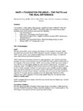
5 The following message will appear if the communicator has a previous version of the device descriptors (DDs):NOTICE: Upgrade the communicator software to access new XMTR functions. Continue with old description?NoteIf this notice does not appear, the latest DD is the latest version is not available, the communicator will communicate properly, but when the Transmitter is configured some new capabilities may not be prevent this from happening, upgrade to the latest DD or answer NO to the question and default to the generic Transmitter functionality. Figure 1. Connecting a Communicator to a Bench LoopA. Power/signal terminalsB. 250 RL 1100 C. Power hart revision modeIf the hart configuration tool is not capable of communicating with hart Revision 7, the Rosemount 3144P Transmitter will load a generic menu with limited capability.
6 The following procedures will switch the hart revision mode from the generic Setup > Device Information > Identification > To change to hart Revision 5, Enter: HART5 in the Message fieldb. To change to hart Revision 7, Enter: HART7 in the Message fieldFunctionHART 5 Fast KeysHART 7 Fast Keys2-wire Offset Sensor 12, 2, 1, 52, 2, 1, 62-wire Offset Sensor 22, 2, 2, 52, 2, 2, 6 Alarm values2, 2, 5, 62, 2, 5, 6 Analog calibration3, 4, 53, 4, 5 Analog output2, 2, 52, 2, 5 ACor*BQuick Start Guide5 December 2017 Average Temperature setup2, 2, 3, 32, 2, 3, 3 Burst modeN/A2, 2, 8, 4 Comm statusN/A1, 2 Configure additional messagesN/A2, 2, 8, 4, 7 Configure Hot Backup 2, 2, 4, 1, 32, 2, 4, 1, 3 Date2, 2, 7, 1, 22, 2, 7, 1, 3 Descriptor 2, 2, 7, 1, 32, 2, 7, 1, 4 Device Information2, 2, 7, 12, 2, 7, 1 Differential Temperature setup2, 2, 3, 12, 2, 3, 1 Filter 50/60 Hz 2, 2, 7, 5, 12, 2, 7, 5, 1 Find deviceN/A3, 4, 6, 2 First good Temperature setup2, 2, 3, 22, 2, 3.
7 2 Hardware revision1, 8, 2, 31, 11, 2, 3 hart lockN/A2, 2, 9, 2 Intermittent sensor detect2, 2, 7, 5, 22, 2, 7, 5, 2 Lock statusN/A1, 11, 3, 7 Long tagN/A2, 2, 7, 2 Loop test 3, 5, 13, 5, 1 LRV (Lower Range Value)2, 2, 5, 5, 32, 2, 5, 5, 3 Message2, 2, 7, 1, 42, 2, 7, 1, 5 Open sensor holdoff2, 2, 7, 42, 2, 7, 4 Percent range2, 2, 5, 42, 2, 5, 4 Sensor 1 configuration2, 2, 12, 2, 2 Sensor 1 serial number 2, 2, 1, 72, 2, 1, 8 Sensor 1 setup2, 2, 12, 2, 1 Sensor 1 statusN/A2, 2, 1, 2 Sensor 1 type2, 2, 1, 22, 2, 1, 3 Sensor 1 unit2, 2, 1, 42, 2, 1, 5 Sensor 2 configuration 2, 2, 22, 2, 2 Sensor 2 serial number2, 2, 2, 72, 2, 2, 8 Sensor 2 setup2, 2, 22, 2, 2 Sensor 2 statusN/A2, 2, 2, 2 Sensor 2 type2, 2, 2, 22, 2, 2, 3 Sensor 2 unit2, 2, 2, 42, 2, 2, 5 Sensor drift alert2, 2, 4, 22, 2, 4, 2 Simulate device variablesN/A3, 5, 2 Software revision1, 8, 2, 41, 11, 2.
8 4 FunctionHART 5 Fast KeysHART 7 Fast KeysDecember 20176 Quick Start the alarms and lock deviceThe Rosemount 3144P Transmitter comes with hardware switches to configure alarms and lock the device. Use the following procedure to set the switches:Without an LCD display1. Set the loop to manual (if applicable) and disconnect the Remove the electronics housing Set the alarm and security switches to the desired position. Reattach housing Apply power and set the loop to automatic an LCD display1. Set the loop to manual (if applicable) and disconnect the Remove the electronics housing Unscrew the LCD display screws and slide the meter straight Set the alarm and security switches to the desired Reattach the LCD display and electronics housing cover (consider the LCD display orientation rotate in 90 degree increments).
9 6. Apply power and set the loop to automatic the transmitterMount the Transmitter at a high point in the conduit run to prevent moisture from draining into the Transmitter field mount installation1. Mount the thermowell to the process container wall. 2. Install and tighten thermowells. 3. Perform a leak Attach any necessary unions, couplings, and extension fittings. Seal the fitting threads with an approved thread sealant, such as silicone or PTFE tape (if required).Ta g2, 2, 7, 1, 12, 2, 7, 1, 1 Terminal Temperature units2, 2, 7, 32, 2, 7, 3 URV (Upper Range Value)2, 2, 5, 5, 22, 2, 5, 5, 2 Variable mapping2, 2, 8, 52, 2, 8, 5 Thermocouple diagnostic2, 1, 7, 12, 1, 7, 1 Min/max tracking2, 1, 7, 22, 1, 7, 2 Rosemount X-well configurationN/A2, 2, 1, 11 FunctionHART 5 Fast KeysHART 7 Fast KeysQuick Start Guide7 December 20175.
10 Screw the sensor into the thermowell or directly into the process (depending on installation requirements).6. Verify all sealing Attach the Transmitter to the thermowell/sensor assembly. Seal all threads with an approved thread sealant, such as silicone or PTFE tape (if required).8. Install field wiring conduit into the open Transmitter conduit entry (for remote mounting) and feed wires into the Transmitter Pull the field wiring leads into the terminal side of the housing. 10. Attach the sensor leads to the Transmitter sensor terminals (the wiring diagram is located inside the housing cover). 11. Attach and tighten both Transmitter ThermowellB. Extension (nipple)C. Union or couplingD. Conduit for field wiring (DC power)E. Extension fitting lengthTy p i c a l r e m o te m ount installation1.