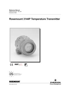
Transcription of Rosemount 3144P Temperature Transmitter - …
1 Reference Manual00809-0100-4021, Rev JBApril 2018 Rosemount 3144P Temperature Transmitterwith Rosemount X-well Technology1 Reference Manual 00809-0100-4021, Rev JBContentsApril 2018 Contents 1 Section 1: this manual.. 3144P revisions.. HART revision capability .. 5 2 Section 2: messages .. considerations .. or corrosive environments .. and position .. compatibility .. the loop to manual .. the switches .. North American installation .. European installation .. X-well installation .. conjunction with a Rosemount 333 HART Tri-Loop (HART/4 20 mA only) .. display .. installation (HART/4 20 mA only) .. 20 mA .. Fieldbus.. connections .. supply .. 25 Contents2 Reference Manual00809-0100-4021, Rev JBContentsApril 2018 Contents 3 Section 3: HART .. HART revision capability .. messages .. Communicator.
2 The HART communication software .. dashboard menu tree .. dashboard Fast Key sequences .. configuration data .. output .. output .. mapping .. configuration .. type and connections .. units .. 1 serial number .. 2 serial number .. RTD offset .. (body) Temperature .. configuration .. X-well Technology configuration .. Rosemount X-well technology with a Field Communicator.. output configuration .. variable damping .. and saturation .. output .. display options .. information .. tag .. filtering.. Hz filter .. reset .. 943 Reference Manual 00809-0100-4021, Rev JBContentsApril sensor detect .. threshold.. sensor holdoff.. and service.. test .. communication .. with the HART Tri-Loop .. frequency .. the Transmitter .. input trim .. calibrator and EMF compensation .. matching.
3 Output trim or scaled output trim .. trim .. output trim .. display .. 132 4 Section 4: FOUNDATION Fieldbus .. messages .. block information .. description .. address.. Active Scheduler (LAS).. Fieldbus function blocks .. block (index number 1000) .. Transducer Block (index number 1100) .. display Transducer Block (index number 1200) .. Input Block (index number 1400, 1500, 1600, and 1700) .. Block (index number 1800 and 1900) .. selector (index number 2000) .. splitter (index number OSPL 2300) .. (index number 2200) .. 1374 Reference Manual00809-0100-4021, Rev JBContentsApril characterizer (index number 2100).. block .. and Features_Sel .. alerts .. actions for Plantweb alerts .. actions for field diagnostics per NE107 .. block diagnostics.. transducer block .. transducer block diagnostics.
4 Display transducer block .. meter configuration .. display transducer block diagnostics .. Backup transducer .. Input (AI) .. the AI block .. alarms.. features .. input diagnostics.. the Transmitter .. diagnostics .. process monitoring (SPM) .. configuration .. guides .. Fieldbus.. display .. 167 5 Section 5: Operation and messages .. terminal (HART /4 20 mA only).. checkout .. housing .. diagnostics logging .. 1715 Reference Manual 00809-0100-4021, Rev JBContentsApril of materials .. 171 6 Section 6: Safety Instrumented Systems (SIS) certification .. certified identification .. and saturation levels .. and maintenance .. test .. proof test 1 .. proof test 2 .. proof test 3 .. rate data .. values .. life.. parts.. 177 AAppendix A: Reference Certifications .. Information, Specifications, and Drawings.
5 1796 Reference Manual00809-0100-4021, Rev JBContentsApril 2018 Contents3 Reference Manual 00809-0100-4021, Rev JBTitle PageApril 2018 Title PageRosemount 3144P Temperature TransmitterNOTICERead this manual before working with the product. For personal and system safety, and for optimum product performance, make sure you thoroughly understand the contents before installing, using, or maintaining this the United States, Emerson has two toll-free assistance numbers:Customer Central Technical support, quoting, and order-related (7:00 am to 7:00 pm CST)North American Response Center Equipment service (24 hours)International(952)-906-8888 The products described in this document are NOT designed for nuclear-qualified applications. Using non-nuclear qualified products in applications that require nuclear-qualified hardware or products may cause inaccurate information on Rosemount nuclear-qualified products, contact your local Emerson Sales Manual00809-0100-4021, Rev JBTitle PageApril 2018 Title PageFailure to follow these installation guidelines could result in death or serious injury.
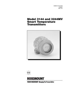
6 Make sure only qualified personnel perform the shock could cause death or serious injury. Use extreme caution when making contact with the leads and could result in death or serious injury. Do not remove the connection head cover in explosive atmospheres when the circuit is live. Before powering a FOUNDATION Fieldbus segment in an explosive atmosphere, make sure the instruments in the loop are installed in accordance with intrinsically safe or non-incendive field wiring practices. Verify that the operating atmosphere of the Transmitter is consistent with the appropriate hazardous locations certifications. All connection head covers must be fully engaged to meet explosion-proof leaks could result in death or serious injury. Do not remove the thermowell while in operation. Install and tighten thermowells and sensors before applying Manual 00809-0100-4021, Rev JBIntroductionApril 20181 IntroductionSection this manualThe sections in this manual provide information on installing, operating, and maintaining the Rosemount 3144P Temperature Transmitter .
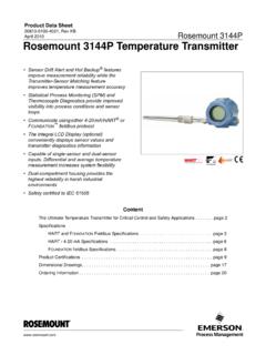
7 The sections are organized as follows: Section 2: Installation contains mechanical and electrical installation instructions. Section 3: HART Commissioning contains techniques for properly commissioning the device. Section 4: Foundation Fieldbus Configuration provides instruction on commissioning and operating Rosemount 3144P Transmitter . Information on software functions, configuration parameters, and online variables is also included. Section 5: Operation and Maintenance contains operation and maintenance techniques. Section 6: Safety Instrumented Systems (SIS) Requirements provides identification, installation, configuration, operation and maintenance, and inspection information for Safety Instrumented Systems. Appendix A: Reference Data supplies procedure on how to get the specifications, ordering information, and product Industry-leading Temperature Transmitter delivers unmatched field reliability and innovative process measurement solutions: Rosemount X-well Technology provides a Complete Point Solution for accurately measuring process Temperature in monitoring applications without the requirement of a thermowell or process penetration Superior accuracy and stability Dual and single sensor capability with universal sensor inputs (RTD, T/C, mV, ohms) Comprehensive sensor and process diagnostics offering IEC 61508 safety certification Dual-compartment housing Large LCD display Selectable HART Revision (5 and 7) or FOUNDATION Fieldbus protocolsImprove efficiency with best-in-class product specifications and capabilities.
8 Reduce maintenance and improve performance with industry leading accuracy and stability Improve measurement accuracy by 75 percent with Transmitter -Sensor Matching Ensure process health with system alerts and easy to use Device Dashboards Easily check device status and values on local LCD display with large percent range graph Achieve high reliability and installation ease with the industry's most rugged dual compartment design2 Reference Manual00809-0100-4021, Rev JBIntroductionApril 2018 IntroductionOptimize measurement reliability with diagnostics designed for any protocol on any host system. Thermocouple Degradation Diagnostic monitors the health of a thermocouple loop, enabling preventative maintenance Minimum and Maximum Temperature Tracking tracks and records Temperature extremes of the process sensors and the ambient environment Sensor Drift Alert detects sensor drift and alerts the user The Hot Backup feature provides Temperature measurement redundancyRefer to the following literature for a full range of compatible connection heads, sensors, and thermowells provided by Emerson : Rosemount Volume 1 Temperature Sensors and Accessories Product Data Sheet, Rosemount DIN-Style Temperature Sensors and Thermowells (Metric) Product Data Sheet, 3144P revisionsHART ProtocolThe initial release of the Rosemount 3144P HART was device revision 3.
9 Each additional revision contains incremental improvements. Ta b l e 1 - 1 summarizes these 1-1. HART RevisionsSoftware release dateIdentify deviceField device driverReview instructionsNAMUR software revisionNAMUR hardware revisionHART software revision(1)1. NAMUR Software Revision is located in the hardware tag of the device. HART Software Revision can be read using a HART capable configuration universal revision(2)2. Device Driver file names use Device and DD Revision, 10_07. HART Protocol is designed to enable legacy driver revisions to continue to communicate with new HART devices. To access this functionality, the new device driver must be downloaded. It is recommended to download the new device driver to ensure new revision Manual document (3)3. Rosemount X-well sensor (4) (4)4. HART Revision 5 and 7 Selectable, thermocouple degradation diagnostic, min/max (4)Feb-2007N/AN/A154 Dec-2003N/AN/AN/A533 Reference Manual 00809-0100-4021, Rev JBIntroductionApril 2018 IntroductionFOUNDATION FieldbusThe following table summarizes the Rosemount 3144P FOUNDATION Fieldbus revision 1-2.
10 FOUNDATION Fieldbus RevisionsDevice revisionSoftwarerevisionHardwarerevision NAMUR software revisionNAMUR hardware revisionDescriptionDateRev releaseMar. 2004 Rev product maintenance, softwareSep. 2004 Rev product maintenance, hardwareDec. 2004 Rev update Oct. 2005 Rev obsolescence hardware change and software to support the hardware 2007 Rev Sensor and Process Diagnostic Release (D01): Thermocouple Degradation Diagnostic and Minimum and Maximum Temperature TrackingNov. 20084 Reference Manual00809-0100-4021, Rev JBIntroductionApril 2018 IntroductionRev Compliance to ITK Addition of NE107 device diagnostic information. Ease of use improvements including: Hot Backup functionality has been moved to the transducer block, allowing easier configuration from the DD Device is shipped with the simulate switch ON, allowing device alerts simulation without cover removal Device has unique block names using the last four digits (XXXX) of the output board serial number, AI_1400_XXXX All blocks are instantiated before shipping, including model option code dependent blocks.