Transcription of Rosemount 644 Temperature Transmitter - …
1 Quick Start Guide00825-0200-4728, Rev GBAugust 2017 NoteBefore installing the Transmitter , confirm the correct device driver is loaded on the host systems. See page 3 for system 644 Temperature Transmitter with 4 20 mA HART Protocol (Revision 5 and 7) August 20172 Quick Start GuideNOTICEThis guide provides basic guidelines for Rosemount 644 Transmitters. It does not provide instructions for configuration, diagnostics, maintenance, service, troubleshooting, explosion-proof, flameproof, or intrinsically safe ( ) installations. Refer to the Rosemount 644 Reference Manual for more instruction. The manual and this guide is also available electronically on could result in death or serious of this Transmitter in an explosive environment must be in accordance with the appropriate local, national, and international standards, codes, and practices.
2 Review the approvals section of the Rosemount 644 Reference Manual for any restrictions associated with a safe installation. Before connecting a HART-based communicator in an explosive atmosphere, make sure the instruments in the loop are installed in accordance with intrinsically safe or non-incendive field wiring shock can result in death or serious injury. Avoid contact with the leads and the terminals. High voltage may be present on leads, which can cause electrical entries Unless marked, the conduit/cable entries in the Transmitter housing use a 1/2 14 NPT thread form. Entries marked M20 are M20 thread form. On devices with multiple conduit entries, all entries will have the same thread form. Only use plugs, adapters, glands, or conduit with a compatible thread form when closing these entries.
3 When installing in a hazardous location, use only appropriately listed or Ex certified plugs, adapters, or glands in cable/conduit readiness .. 3 Transmitter installation .. 3 Safety instrumented systems .. 17 Product Certifications .. 18 Quick Start Guide3 August HART Revision capability If using HART based control or asset management systems, confirm the HART capability of those systems prior to Transmitter installation. Not all systems are capable of communicating with HART Revision 7 Protocol. This Transmitter can be configured for either HART Revision 5 or 7. For instructions on how to change the HART Revision of your Transmitter , see Verify configuration on page correct device driver 1. Verify the latest Device Driver files are loaded on your systems to ensure proper Download the latest Device Driver at 644 Transmitter device revisions and filesTable 1 provides the information necessary to ensure the correct Device Driver files and documentation are being the alarm switchSet the Rosemount 644 Transmitter alarm switch before putting the device into Set the loop to manual (if applicable) and disconnect the power2.
4 Remove the LCD display by detaching from the Transmitter (if applicable).3. Set the switch to the desired position (H indicates High, L indicated Low).4. Reattach the LCD display to the Transmitter (if applicable).5. Reattach the housing cover. Ensure covers must be fully engages to meet explosion-proof 1. Rosemount 644 Device Revisions and FilesSoftware dateNAMUR software revisionHART software revisionHART universal revision(1)1. NAMUR software revision is located on the hardware tag of the device. HART software revision can be read using a HART communication revision(2)2. Device Driver file names use Device and DD Revision, 10_01. HART Protocol is designed to enable legacy device driver revisions to continue to communicate with new HART devices.
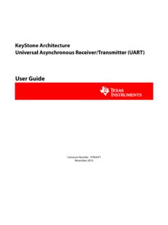
5 To access new functionality, the new Device Driver must be downloaded. It is recommended to download new Device Driver files to ensure full document numberChanges to software(3)3. HART Revision 5 and 7 Selectable, Dual Sensor support, Safety Certified, Advanced Diagnostics (if ordered), Enhanced Accuracy and Stability (if ordered).June Footnote 3 for list of 20174 Quick Start Guide6. Apply power and set the loop to automatic control (if applicable).Figure 1. Alarm Switch PlacementA. Alarm switchNoteIf using an LCD display, remove the display by detaching it from the top of the device, set the switch to the desired position, reattach the LCD display, and reattach the housing cover. Enclosure covers must be fully engaged to meet explosion-proof configurationVerify the configuration of the Rosemount 644 Transmitter device upon receiving your Transmitter using any HART-compliant configuration tool.
6 See the Rosemount 644 Reference Manual for configuration instructions using AMS Device Rosemount 644 Transmitter communicates using the Field Communicator (communication requires a loop resistance between 250 and 1100 ohms). Do not operate when power is below 12 Vdc at the Transmitter terminal. See Rosemount 644 Reference Manual and Field Communicator Reference Manual for more configuration with a Field CommunicatorA Rosemount 644 DD (Device Descriptor) must be installed on the Field Communicator to verify the configuration. Fast Key sequences for the latest DD are shown in Table 2 on page 5. For Fast Key sequences using legacy DD's, contact your local Emerson representative. Perform the following steps to determine if an upgrade is Connect the sensor (see the wiring diagram located on the device s top label).
7 Rosemount 644 TransmitterRosemount 644 Field MountAQuick Start Guide5 August 20172. Connect the bench power supply to the power terminals ( + or ).3. Connect a Field Communicator to the loop across a loop resistor or at the power/signal terminals on the The following message will appear if the communicator has a previous version of the DDs:Device Description Not Device Description for manufacturer 0x26 model 0x2618 dev rev 8/9 is not installed on the System Programming Utility for details on Device Description you wish to proceed in forward compatibility mode?If this notice does not appear, the latest DD is installed. If the latest version is not available, the communicator will communicate properly, however, when the Transmitter is configured to utilize advanced Transmitter features, there will be trouble communicating and a prompt to turn off the communicator will display.
8 To prevent this from happening, upgrade to the latest DD or answer NO to the question and default to the generic Transmitter recommends installing the latest DD to access the complete functionality. Visit for information on updating the DD Communicator user interfaceTwo user interfaces are available to configure this device. The Device Revision 8 and 9 (HART 5 and 7), DD Revision 1 Fast Key Sequence in Table 2 may be used for Transmitter configuration and 2. Device Dashboard Field Communicator InterfaceTable 2. Device Revision 8 and 9 (HART 5 and 7), DD Revision 1 Fast Key SequenceFunctionHART 5 HART 7 Alarm Values2, 2, 5, 62, 2, 5, 6 Analog Calibration3, 4, 53, 4, 5 Analog Output 2, 2, 5, 12, 2, 5, 1 August 20176 Quick Start GuideAverage Temperature Setup 2, 2, 3, 32, 2, 3, 3 Burst Mode 2, 2, 8, 42, 2, 8, 4 Comm StatusN/A1, 2 Configure additional messagesN/A2, 2, 8, 4, 7 Configure Hot Backup 2, 2, 4, 1, 32, 2, 4, 1, 3D/A Trim3, 4, 4, 13, 4, 4, 1 Damping Values2, 2, 1, 52, 2, 1, 6 Date2, 2, 7, 1, 22, 2, 7, 1, 3 Display Setup2, 1, 42, 1, 4 Descriptor 2, 2, 7, 1, 42, 2, 7, 1, 5 Device Information 1, 8, 11, 8, 1 Differential Temperature Setup 2, 2, 3, 12, 2, 3, 1 Drift Alert 2, 2, 4, 22, 2, 4, 2 Filter 50/60 Hz 2, 2, 7, 4, 12, 2, 7, 4, 1 First Good Temperature Setup2.
9 2, 3, 22, 2, 3, 2 Hardware Revision 1, 8, 2, 3 1, 8, 2, 3 HART LockN/A2, 2, 9, 2 Intermittent Sensor Detect2, 2, 7, 4, 22, 2, 7, 4, 2 Loop Test 3, 5, 13, 5, 1 Locate DeviceN/A3, 4, 6, 2 Lock StatusN/A1, 8, 3, 8 LRV (Lower Range Value) 2, 2, 5, 5, 3 2, 2, 5, 5, 3 LSL (Lower Sensor Limit)2, 2, 1, 7, 22, 2, 1, 8, 2 Message 2, 2, 7, 1, 3 2, 2, 7, 1, 4 Open Sensor Holdoff 2, 2, 7, 32, 2, 7, 3 Percent Range 2, 2, 5, 2 2, 2, 5, 2 Sensor 1 Configuration2, 1, 12, 1, 1 Sensor 2 Configuration2, 1, 12, 1, 1 Sensor 1 Serial Number 2, 2, 1, 62, 2, 1, 7 Sensor 2 Serial Number2, 2, 2, 72, 2, 2, 8 Sensor 1 Type 2, 2, 1, 22, 2, 1, 3 Sensor 2 Type2, 2, 2, 22, 2, 2, 3 Sensor 1 Unit 2, 2, 1, 42, 2, 1, 5 Sensor 2 Unit 2, 2, 2, 42, 2, 2, 5 Sensor 1 StatusN/A2, 2, 1, 2 Sensor 2 StatusN/A2, 2, 2, 2 Table 2.
10 Device Revision 8 and 9 (HART 5 and 7), DD Revision 1 Fast Key SequenceFunctionHART 5 HART 7 Quick Start Guide7 August 2017 Input or verify Callendar Van-Dusen constantsIf sensor matching is being used with this combination of a Transmitter and sensor, verify the constants From the HOME screen, select 2 Configure, 2 Manual Setup, 1 Sensor. 2. Set the control loop to manual and select At the ENTER SENSOR TYPE prompt, select Cal At the ENTER SENSOR CONNECTION prompt, select the appropriate number of Enter the Ro, Alpha, Delta, and Beta values from the stainless steel tag attached to the special-order sensor when Return the control loop to automatic control and select To disable the Transmitter -sensor matching feature from the HOME screen select 2 Configure, 2 Manual Setup, 1 Sensor, 10 Sensor Choose the appropriate sensor type from the ENTER SENSOR TYPE configuration with Local Operator Interface (LOI)The optional LOI can be used for commissioning the device.