Transcription of Rosemount 8700 Series - Emerson Electric
1 Manual 00809-0100-4727, Rev EAOctober 2010 Rosemount 8700 SeriesMagnetic Flowmeter SensorsReference Manual 00809-0100-4727, Rev EAOctober 2010 Rosemount 8700 Magnetic Flowmeter SensorsNOTICERead this manual before working with the product. For personal and system safety, and for optimum product performance, make sure you thoroughly understand the contents before installing, using, or maintaining this the United States, Rosemount Inc. has two toll-free assistance Central: 1-800-999-9307(7:00 to 7:00 CST)Technical support, quoting, and order-related American1-800-654-7768 (24 hours a day Includes Canada) Response Center: Equipment service equipment service or support needs outside the United States, your local Emerson Process Management products described in this document are NOT designed for nuclear-qualified applications. Using non-nuclear qualified products in applications that require nuclear-qualified hardware or products may cause inaccurate readings.
2 For information on Rosemount nuclear-qualified products, contact your local Emerson Process Management Sales Manual 00809-0100-4727, Rev EAOctober 2010 Rosemount 8700 of ContentsSECTION 1 IntroductionManual Description .. 1-1 Safety Information .. 1-2 Return of Materials .. 1-2 SECTION 2 InstallationSafety Messages .. 2-1 Sensor Handling .. 2-3 Sensor Mounting .. 2-4 Upstream/Downstream piping .. 2-4 Sensor Orientation .. 2-4 Flow Direction .. 2-6 Installation (Flanged Sensor).. 2-7 Gaskets .. 2-7 Flange Bolts .. 2-7 Installation (Wafer Sensor) .. 2-10 Gaskets .. 2-10 Flange Bolts .. 2-11 Installation (Sanitary Sensor).. 2-12 Gaskets .. 2-12 Alignment and Bolting.. 2-12 Process Leak Protection (Optional) .. 2-13 Standard Housing Configuration .. 2-13 Relief Valves.. 2-14 Process Leak Containment .. 2-14 Conduit Ports and Connections .. 2-15 Conduit Cables .. 2-16 Electrical Considerations .. 2-17 Sensor Connections .. 2-18 Rosemount Sensors.
3 2-18 Transmitter to Sensor Wiring .. 2-18 SECTION 3 Operation and MaintenanceCalibration .. 3-1 Grounding .. 3-1 Material Selection .. 3-3 Magnetic Flowmeter Sizing .. 3-4 reference Manual00809-0100-4727, Rev EAOctober 2010 Rosemount 8700 SeriesTOC-2 SECTION 4 Maintenance andTroubleshootingSafety Information .. 4-1 Installation Check and Guide.. 4-2 Diagnostic Messages.. 4-3 Transmitter Troubleshooting .. 4-5 Quick Troubleshooting.. 4-7 Step 1: Wiring Errors .. 4-7 Step 2: Process Noise .. 4-7 Step 3: Installed Sensor Tests .. 4-7 Step 4: Uninstalled Sensor Tests .. 4-9 APPENDIX AReference DataRosemount 8700 Series Product Specifications Overview .. A-1E- Series Performance Specifications .. A-5 High Signal System Performance Specifications.. A-7 Rosemount Flanged Sensor Specifications.. A-9 Flanged Sensor Functional Specifications.. A-9 Flanged Sensor Physical Specifications .. A-11 Rosemount 8711 Wafer Sensor Specifications .. A-138711 Functional Specifications.
4 A-138711 Physical Specifications .. A-14 Rosemount 8721 Sanitary Sensor Specifications .. A-168721 Functional Specifications .. A-168721 Physical Specifications .. A-17 Dimensional Drawings .. A-20 Rosemount Flanged Sensors .. A-36 Rosemount High-Signal Magmeter System.. A-36 Options (Include with selected model number) .. A-39 Rosemount 8711 Wafer Sensors .. A-43 Options (Include with selected model number) .. A-45 Rosemount 8721 Hygienic Sensors .. A-46 Options (Include with selected model number) .. A-47 Tagging.. A-48 Ordering Procedure .. A-48 Standard Configuration.. A-48 Cable Requirements for Remote Transmitters .. A-48 APPENDIX BApprovalsApproved Manufacturing Locations .. B-1 European Directive Information .. B-1 ATEX Directive .. B-1 European Pressure Equipment Directive (PED) (97/23/EC) .. B-1 Electro Magnetic Compatibility (EMC) (2004/108/EC) .. B-2 Low Voltage Directive (2006/95/EC) .. B-2 Other important guidelines.
5 B-2 IECEx Certificates .. B-2 Hazardous Locations Product Approvals Offering.. B-3 Hazardous Location Certifications .. B-7 North American Certifications .. B-7 Canadian Standards Association (CSA).. B-7 European Certifications .. B-7 International Certifications .. B-8 reference Manual 00809-0100-4727, Rev EAOctober 2010 Rosemount 8700 1 IntroductionManual Description ..page 1-1 Safety Information ..page 1-2 Return of Materials ..page 1-2 MANUAL DESCRIPTIONThe Rosemount Series 8700 Magnetic Flowmeter System combines separate sensor and transmitter units. This manual is designed to assist in the installation and operation of Rosemount 8705, 8707 High-Signal, and 8711 Magnetic Flowmeter Sensor. Section 1: Introduction Manual description Safety information Return of materialSection 2: Installation Installation instructionsSection 3: Operation and Maintenance Sensor calibration number Sensor configuration 4: Maintenance and Troubleshooting Troubleshooting procedures Electrical circuit diagramsAppendix A: reference Data Instructions for removing and replacing the field-removable electrode assemblyAppendix B: ApprovalsAppendix B: Approvals Approved Manufacturing Locations European Directive Information Hazardous Locations Product Approvals Offering Hazardous Location CertificationsAttempting to install and operate the Rosemount 8705, 8707 High-Signal, or 8711 Magnetic Flowmeter Sensor without reviewing the instructions contained in this manual could result in personal injury or equipment damage.
6 reference Manual00809-0100-4727, Rev EAOctober 2010 Rosemount 8700 Series1-2 SAFETY INFORMATIONP rocedures and instructions in this manual may require special precautions to ensure the safety of the personnel performing the operations. Refer to the safety messages listed at the beginning of each section before performing any OF MATERIALSTo expedite the return process outside the United States, contact the nearest Rosemount the United States and Canada, call the North American Response Center using the 800-654-RSMT (7768) toll-free number. The Response Center, available 24 hours a day, will assist you with any needed information or center will ask for product model and serial numbers, and will provide a Return Material Authorization (RMA) number. The center will also ask for the name of the process material to which the product was last products exposed to a hazardous substance may result in death or serious injury. If the product being returned was exposed to a hazardous substance as defined by OSHA, a copy of the required Material Safety Data Sheet (MSDS) for each hazardous substance identified must be included with the returned North American Response Center will detail the additional information and procedures necessary to return goods exposed to hazardous Safety Information on page 4-1 for complete warning Manual 00809-0100-4727, Rev EAOctober 2010 Rosemount 8700 2 InstallationSafety Messages.
7 Page 2-1 Sensor Handling ..page 2-3 Sensor Mounting ..page 2-4 Installation (Flanged Sensor) ..page 2-7 Installation (Wafer Sensor) ..page 2-10 Installation (Sanitary Sensor) ..page 2-12 Process Leak Protection (Optional) ..page 2-13 Process Leak Protection (Optional) ..page 2-13 Sensor Connections ..page 2-18 This section covers the steps required to physically install the magnetic sensor. Instructions and procedures in this section may require special precautions to ensure the safety of the personnel performing the operations. Please refer to the following safety messages before performing any operation in this MESSAGESThis symbol is used throughout this manual to indicate that special attention to warning information is to follow these installation guidelines could result in death or serious injury:Installation and servicing instructions are for use by qualified personnel only. Do not perform any servicing other than that contained in the operating instructions, unless qualified.
8 Verify that the operating environment of the sensor and transmitter is consistent with the appropriate hazardous area not connect a Rosemount transmitter to a non- Rosemount sensor that is located in an explosive Manual00809-0100-4727, Rev EAOctober 2010 Rosemount 8700 Series2-2 Explosions could result in death or serious injury: Installation of this transmitter in an explosive environment must be in accordance with the appropriate local, national, and international standards, codes, and practices. Please review the approvals section of this reference manual for any restrictions associated with a safe installation. Electrical shock can result in death or serious injuryAvoid contact with the leads and terminals. High voltage that may be present on leads can cause electrical sensor liner is vulnerable to handling damage. Never place anything through the sensor for the purpose of lifting or gaining leverage. Liner damage can render the sensor avoid possible damage to the sensor liner ends, do not use metallic or spiral-wound gaskets.
9 If frequent removal is anticipated, take precautions to protect the liner ends. Short spool pieces attached to the sensor ends are often used for flange bolt tightening is crucial for proper sensor operation and life. All bolts must be tightened in the proper sequence to the specified torque limits. Failure to observe these instructions could result in severe damage to the sensor lining and possible sensor Process Management can supply lining protectors to prevent liner damage during removal, installation, and excessive bolt Manual 00809-0100-4727, Rev EAOctober 20102-3 Rosemount 8700 SeriesSENSOR HANDLINGH andle all parts carefully to prevent damage. Whenever possible, transport the system to the installation site in the original shipping containers. PTFE-lined sensors are shipped with end covers that protect it from both mechanical damage and normal unrestrained distortion. Remove the end covers just before sensors with a lifting lug on each flange make the sensor easier to handle when it is transported and lowered into place at the installation site.
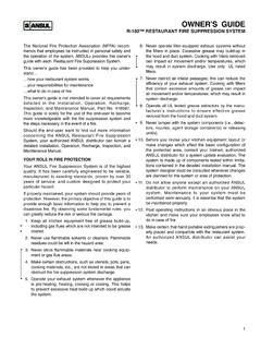
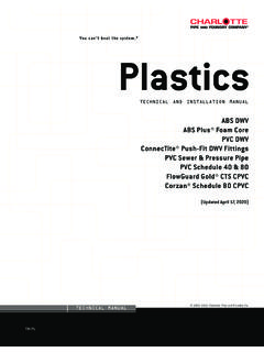
10 Flanged sensors that do not have lugs must be supported with a lifting sling on each side of the housing. Figure 2-1 shows sensors correctly supported for handling and installation. Notice the plywood end pieces are still in place to protect the sensor liner during 2-1. Rosemount 8705 Sensor Support for HandlingSee Safety Messages on pages 2-1 and 2-2 for complete warning Lifting LugsWith Lifting LugsReference Manual00809-0100-4727, Rev EAOctober 2010 Rosemount 8700 Series2-4 SENSOR MOUNTINGP hysical mounting of a sensor is similar to installing a typical section of pipe. Conventional tools, equipment, and accessories (bolts, gaskets, and grounding hardware) are required. Upstream/DownstreamPipingTo ensure specification accuracy over widely varying process conditions, install the sensor a minimum of five straight pipe diameters upstream and two pipe diameters downstream from the electrode plane (see Figure 2-2).Figure 2-2. Upstream and Downstream Straight Pipe DiametersSensor OrientationThe sensor should be installed in a position that ensures the sensor remains full during operation.