Transcription of Rosemount 8750W Magnetic Flowmeter System
1 Product data Sheet00813-0300-4750, Rev CBMay 2019 Rosemount 8750W Magnetic FlowmeterSystemfor Utility, Water, and Wastewater Applications Best in class value with performance, reliability, and diagnostics suited for monitoring applications Reliable all welded coil housing and lightweight sensor design rated to IP68 Available in 4 20mA with HART , FOUNDATION Fieldbus, Modbus RS-485, Process Diagnostics, and SMART Meter Verificationto improve reliability and performance Available with drinking water certificationsProduct Selection GuideThe Rosemount 8750W Magnetic Flowmetersensor is available in a flanged style and transmitter is available in remote and integraltransmitter configurations to ensure compatibility with all utility, water, and wastewater selectionTransmitterGeneral characteristicsField mount Integral and remote configurations available HART/Analog and Pulse outputs available FOUNDATION Fieldbus and pulse output available Modbus RS-485 and Pulse output available Advanced Diagnostics available LCD display (optional)
2 With optional optical switch local operator interface(1) Two discrete channels (optional)Wall mount Wall mount configuration HART/Analog and Pulse outputs available Modbus RS-485 and Pulse output available FOUNDATION Fieldbus and pulse output available Advanced Diagnostics available Local LCD display (optional) With optional 15 button tactile key pad(1) Two discrete channels (optional)(1)HART or Modbus protocol Selection 3 Magnetic Flowmeter 4 Ordering 7 Product selectionTable 1: Sensor SelectionSensorGeneral characteristicsFlanged Flanged process connections Welded coil housing -in. (15 mm) to 48-in. (1200 mm) Standard, reference, and bullet-nose electrodes availableSelecting materialsFor guidance on selecting materials, refer to the Rosemount Magnetic Flowmeter Material Selection Guide (00816-0100-3033) ,available at DiagnosticsRosemount diagnostics reduce cost & improve output by enabling new practicesRosemount Magnetic Flowmeters provide device diagnostics that detect and warn of abnormal situations throughout the life of themeter - from installation to maintenance and meter verification.
3 With Rosemount Magnetic Flowmeter diagnostics enabled, plantavailability and throughput can be improved, and costs through simplified installation, maintenance and troubleshooting can 2: Magnetic Flowmeter diagnosticsDiagnostic nameDiagnostic categoryProduct capabilityBasic diagnosticsTunable Empty PipeProcessStandardElectronics TemperatureMeter HealthStandardCoil FaultMeter HealthStandardTransmitter FaultMeter HealthStandardReverse FlowProcessStandardCoil currentMaintenanceStandardElectrode saturationProcess/MaintenanceStandardAdv anced diagnosticsHigh Process NoiseProcessSuite 1 (DA1)Grounding and Wiring FaultInstallationSuite 1 (DA1)Coated Electrode DetectionProcessSuite 1 (DA1)Commanded Smart Meter VerificationMeter HealthSuite 2 (DA2)Continuous Smart Meter VerificationMeter HealthSuite 2 (DA2)May 2.
4 Magnetic Flowmeter diagnostics (continued)Diagnostic nameDiagnostic categoryProduct capability4-20 mA Loop Verification(1)InstallationSuite 2 (DA2)(1)Available with HART output for accessing diagnosticsRosemount Magmeter Diagnostics can be accessed through the Local Operator Interface (LOI), ProLink III , a HART FieldCommunicator(1), and AMS Suite: Intelligent Device Manager(1). Contact your local Rosemount representative to activatediagnostics or for diagnostic availability on existing diagnostics through the LOI for quicker installation, maintenance, and meter verificationRosemount Magnetic Flowmeter Diagnostics are available through the LOI to simplify diagnostics through ProLink III v.
5 (HART)/ProLink III v. (HART, Modbus)Simplify maintenance and troubleshooting practices by utilizing ProLink III to access diagnostics and troubleshootinginformation, log variable data , run SMART Meter Verification, and print verification diagnostics through AMS Intelligent Device Manager(1) for the ultimate valueThe value of the diagnostics increases significantly when AMS Intelligent Device Manager is used. AMS Intelligent Device Managerprovides a simplified screen flow and procedures for how to respond to the diagnostic Flowmeter SizingSelecting the appropriate sensor size is an important step when considering a Magnetic Flowmeter . The physical properties of theprocess fluid, as well as the fluid velocity should be considered.
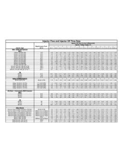
6 It may be necessary to select a flow sensor that is larger or smallerthan the adjacent piping to ensure the fluid velocity is in the recommended flow range for the application. Operation outside these guidelines may also give acceptable 3: Sizing guidelinesApplicationVelocity range (ft/s)Velocity range (m/s)Normal Service0 390 12 Preferred Service2 outside these guidelines may also give acceptable convert flow rate to velocity, use the appropriate factor listed in Table 4 and the following equation:Velocity =Flow RateFactor(1) Available with HART output : English unitsExample: SI unitsMagmeter Size: 4 in. (factor from Table 4 = ) NormalFlow Rate: 300 GPMV elocity =300 (gpm) = ft/sMagmeter Size: 100 mm (factor from Table 4 = )NormalFlow Rate: 800 L/minVelocity =800 (L/min) = m/sTable 4: Line size vs.
7 Conversion factorNominal line size Inches (mm)Gallons per minute factorLiters per minute factor (15) (25) (40) (50) (65) (80) (100) (125) (150) , (200) , (250) , (300) , (350) , (400) , (450) , (500) ,76124 (600)1, ,56430 (750) ,91336 (900)2, ,45140 (1000)3, ,35742 (1050)4, ,10748 (1200)5, ,159 May 5: Line size vs. velocity/rateNominalline size ininches(mm)Minimum/maximum flow rateGallons per minuteLiters per minuteat ft/s(low-flowcutoff)at 1 ft/s(min rangesetting)at 3 ft/sat ft/s(max rangesetting)at (low-flowcutoff)at m/s(min rangesetting)at 1 m/sat 12 m/s(max rangesetting) (15) (25) (40) (50) , (65) , (80) , (100) , , (125) , , (150) , , ,4208 (200) , , ,23810 (250) , , ,62912 (300) , , , , ,53514 (350) , , , , ,84816 (400) , , , , ,08718 (450) , , , , ,90320 (500) , , , ,761129,13724 (600) , , , , ,564186,76930 (750) , , , , ,913298,95936 (900) , , , ,93536,451437,41640 (1000) , ,956143, ,60745,357544,28642 (1050) , ,345162, ,33251,107613,27848 (1200)
8 , , ,14867,159805,908 Upstream and downstream pipingTo ensure specified accuracy over widely varying process conditions, install the sensor with a minimum of five straight pipediameters upstream and two pipe diameters downstream from the electrode 1: Upstream and downstream straight pipe diametersA. Five pipe diameters (upstream)B. Two pipe diameters (downstream)C. Flow directionInstallations with reduced upstream and downstream straight runs are possible. In reduced straight run installations, the metermay not meet accuracy specifications. Reported flow rates will still be highly groundingA reliable ground path is required between the sensor and the process fluid. Optional grounding rings or process referenceelectrodes are available with the sensor to ensure proper grounding.
9 See Table 5 and Table InformationRosemount 8750W Magnetic Flowmeter PlatformThe Rosemount 8750W Magnetic Flowmeter is available in a flanged sensor design. The sensors arefabricated from stainless and carbon steel and welded to provide a sealed coil housing that protectsagainst moisture or other contaminants. Sizes range from 1/2-in. (15 mm) to 48-in. (1200 mm). Thefield mount transmitter has a die cast aluminum housing for excellent reliability. The wall mounttransmitter features an easy to use operator interface. Both transmitter styles are available withadvanced diagnostics to provide the best insight into the process and the meter's starred ( ) offerings represent the most common options, and should be selected for best code structureExample model code with one selection out of each category: 8750W D M T 1 A 1 F P S A 010 C A1 Z5 DA2 AX M4 BD G5 B6 R15 V1 Q4 HR7 WG YFTable 6: Requirements - select one from each available choiceExample codeCategory8750 WBase model Magnetic Flowmeter System (utility, water, and wastewater)DSensor design revision Revision "D"MTransmitter class (Table 8)TTransmitter mount (Table 9)1 Transmitter power (Table 10)May 6.
10 Requirements - select one from each available choice (continued)Example codeCategoryATransmitter outputs (Table 11)1 Conduit entries (Table 12)FSensor style (Table 13)PLining material (Table 14)SElectrode material (Table 15)AElectrode type (Table 16)010 Line size (Table 17)CFlange type and material (Table 18)A1 Flange rating (Table 19)Table 7: Options - select only as neededExample codeCategoryZ5 Hazardous area certifications (Table 20)DA2 Advanced diagnostics (Table 21)AXDiscrete input/output (Table 22)M4 Display (Table 23)BDCertifications (Table 24)G5 Grounding rings (Table 25)B6 Miscellaneous (Table 26)R15 Submergence protection (Table 27)V1 Special paint (Table 28)Q4 Quality certificates (Table 29)HR7 Revision configuration (Table 30)WGWitness inspection (Table 31)YxQuick Start Guide language (Table 32)RequirementsTable 8: Rosemount 8750W transmitter classCodeDescriptionMRevision 4 electronics 0 Spare sensor, no transmitterTable 9.