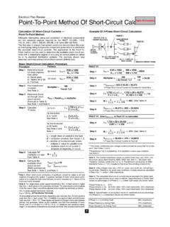
Transcription of ROTORK RANGE
1 Installation andMaintenance InstructionsPublication number E170E Mark 1 Date of issue 12/99 ROTORK RANGEThis instruction manual provides instruction on :-* Manual and electrical (local and remote) operation.* Preparation and installation of the actuator on to the valve.* Subsequent commissioning and adjustment of the Primary Settings for correct valve operation.* Commissioning and adjustment of the actuator Secondary Settings to suit site specific control and indication requirements.* Maintenance - Troubleshooting.* Sales and ROTORK IQ RANGE - THE WORLDS FIRST VALVEACTUATOR THAT YOU CAN COMMISSION ANDINTERROGATE WITHOUT REMOVING the supplied infra-red setting tool to access theactuator set up procedures, point and shoot setting oftorque levels, position limits and all other control andindication functions can be made quickly and convenientlyeven in hazardous diagnostics access information about the controlsystem, valve and actuator status in the form of actuatordisplay Help torque and position can be monitored on thedisplay with a simple key press of the setting actuator containing the setting tool will be identifiedwith a yellow label on the terminal cover.
2 1 Health and Safety22 Storage33 Operating your IQ Operating by Operation The Actuator Display -valve position indication 44 Preparing the Drive IQ7 to IQ35 - Thrust BaseType A IQ7 to IQ35 - Non Thrust Base Type B IQ40 to IQ95 - Thrust Base Types A & AZ IQ40 to IQ95 - Non Thrust Base Type B 75 Mounting the Rising Stem Valves - Top Valve with Gearbox -Side Non Rising Stem Valves - Top Handwheel IQM IQML Linear Drive IQML AdjustingLinear Stroke106 Wiring Earth/Ground Removing Terminal Cable Connecting to Replacing Terminal The Setting The Setting Tool Entering the Setting Setting Mode - password New Checking Procedure Branch The Actuator display Setting/Checking Returning to Valve Position Display168 Commissioning -Primary Actuator Functions17 Primary Functions Index189 Commissioning -Secondary Actuator Functions27 Secondary Functions Index2710 Maintenance, Monitoringand Troubleshooting Help Displays4611 Weights and Measures541 This manual is produced to enablea competent user to install,operate, adjust and inspect RotorkIQ RANGE valve electrical installation,maintenance and use of theseactuators should conform to therequirements of the Electricity atWork Regulations 1989 and theguidance given in the 16th editionof the IEEE Wiring Regulations ,also any other National legislationapplicable.
3 The user shouldtherefore make himself familiar withthese regulations and otherStatutory Provisions relating to thesafe use of this equipment. Alsothe user should be fully aware ofhis duties under the Health andSafety Act mechanical installation shouldbe carried out as outlined in themanual and also in accordancewith the relevant British StandardCodes of the actuator has nameplatesindicating that it is suitable forinstallation in Hazardous Gas Areasthen the actuator is suitable for usein Zone 1 and Zone 2 explosiveatmospheres only. They should notbe installed in atmospheres wheregases are present with an ignitiontemperature less than 135 suitability for lower ignitiontemperatures has been indicatedon the actuator nameplate. Any testinstruments applied to the actuatorshould be of equivalent electrical installation,maintenance and the use of theseactuators should be carried out inaccordance with BS 5345 Part 11976 and BS 5345 Part 3 inspection or repair should beundertaken unless it conforms tothe requirements given in thesestandards, and under nocircumstances should anymodification or alteration be carriedout on the actuator as this could very well invalidate the conditionsunder which the certification wasgrantedAccess to live electrical conductorsof the actuator is forbidden in thehazardous area unless this is doneunder a special permit to work.
4 Otherwise all power should beisolated and the actuator removedto a non hazardous area for repairor persons competent by virtueof their training and experienceshould be allowed to install,maintain and repair these actuatorsand they should carry out this workin accordance with the instructionsgiven in the manual. The user andthose persons working on thisequipment should be familiar withtheir responsibilities under theHealth and Safety at Work etc. Act1974 and relevant StatutoryProvisions relating to their TemperaturesWith excessive use motor surfacetemperature could reach 132 further information andguidance relating to the safeinstallation, maintenance and useof the ROTORK IQ RANGE actuator berequired, this will be provided and Safety12 WARNING:With respect to the handwheel operation of ROTORK electric actuators, under no circumstances should any additional leaver device such as a wheel-key or wrench be applied to the handwheel or in order to develop more force when closing or opening the valve as this may cause damage to the valve and/or actuator or may cause the valve to become stuck in the seated/backseated position.
5 WARNING:With respect to the handwheel operation of ROTORK electric actuators, under no circumstances should any additional leaver device such as a wheel-key or wrench be applied to the handwheel or in order to develop more force when closing or opening the valve as this may cause damage to the valve and/or actuator or may cause the valve to become stuck in the seated/backseated position. WARNING:With respect to the handwheel operation of ROTORK electric actuators, under no circumstances should any additional leaver device such as a wheel-key or wrench be applied to the handwheel or in order to develop more force when closing or opening the valve as this may cause damage to the valve and/or actuator or may cause the valve to become stuck in the seated/backseated position. WARNING:With respect to the handwheel operation of ROTORK electric actuators, under no circumstances should any additional leaver device such as a wheel-key or wrench be applied to the handwheel or in order to develop more force when closing or opening the valve as this may cause damage to the valve and/or actuator or may cause the valve to become stuck in the seated/backseated position.
6 WARNING:With respect to the handwheel operation of ROTORK electric actuators, under no circumstances should any additional leaver device such as a wheel-key or wrench be applied to the handwheel or in order to develop more force when closing or opening the valve as this may cause damage to the valve and/or actuator or may cause the valve to become stuck in the seated/backseated position. WARNING:With respect to the handwheel operation of ROTORK electric actuators, under no circumstances should any additional leaver device such as a wheel-key or wrench be applied to the handwheel or in order to develop more force when closing or opening the valve as this may cause damage to the valve and/or actuator or may cause the valve to become stuck in the seated/backseated position. WARNING:With respect to the handwheel operation of ROTORK electric actuators, under no circumstances should any additional leaver device such as a wheel-key or wrench be applied to the handwheel or in order to develop more force when closing or opening the valve as this may cause damage to the valve and/or actuator or may cause the valve to become stuck in the seated/backseated position.
7 WARNING:With respect to the handwheel operation of ROTORK electric actuators, under no circumstances should any additional leaver device such as a wheel-key or wrench be applied to the handwheel or in order to develop more force when closing or opening the valve as this may cause damage to the valve and/or actuator or may cause the valve to become stuck in the seated/backseated position. WARNING:With respect to the handwheel operation of ROTORK electric actuators, under no circumstances should any additional leaver device such as a wheel-key or wrench be applied to the handwheel or in order to develop more force when closing or opening the valve as this may cause damage to the valve and/or actuator or may cause the valve to become stuck in the seated/backseated position. WARNING:With respect to the handwheel operation of ROTORK electric actuators, under no circumstances should any additional leaver device such as a wheel-key or wrench be applied to the handwheel or in order to develop more force when closing or opening the valve as this may cause damage to the valve and/or actuator or may cause the valve to become stuck in the seated/backseated position.
8 WARNING:With respect to the handwheel operation of ROTORK electric actuators, under no circumstances should any additional leaver device such as a wheel-key or wrench be applied to the handwheel or in order to develop more force when closing or opening the valve as this may cause damage to the valve and/or actuator or may cause the valve to become stuck in the seated/backseated position. WARNING:With respect to the handwheel operation of ROTORK electric actuators, under no circumstances should any additional leaver device such as a wheel-key or wrench be applied to the handwheel or in order to develop more force when closing or opening the valve as this may cause damage to the valve and/or actuator or may cause the valve to become stuck in the seated/backseated position. WARNING:With respect to the handwheel operation of ROTORK electric actuators, under no circumstances should any additional leaver device such as a wheel-key or wrench be applied to the handwheel or in order to develop more force when closing or opening the valve as this may cause damage to the valve and/or actuator or may cause the valve to become stuck in the seated/backseated position.
9 WARNING:With respect to the handwheel operation of ROTORK electric actuators, under no circumstances should any additional leaver device such as a wheel-key or wrench be applied to the handwheel or in order to develop more force when closing or opening the valve as this may cause damage to the valve and/or actuator or may cause the valve to become stuck in the seated/backseated position. WARNING:With respect to the handwheel operation of ROTORK electric actuators, under no circumstances should any additional leaver device such as a wheel-key or wrench be applied to the handwheel or in order to develop more force when closing or opening the valve as this may cause damage to the valve and/or actuator or may cause the valve to become stuck in the seated/backseated position. If your actuator cannot be installedimmediately store it in a dry placeuntil you are ready to wire the actuator has to be installedbut cannot be wired up it isrecommended that the plastictransit cable entry plugs arereplaced with metal plugs which aresealed with PTFE ROTORK double sealedconstruction will preserve internalelectrical components perfectly ifleft is not necessary to remove anyelectrical compartment covers inorder to commission the cannot accept responsibilityfor deterioration caused on siteonce the covers are ROTORK actuator has beenfully tested before leaving thefactory to give years of trouble freeoperation providing it is correctly.
10 Commissioned installed and 1To engage handwheel drivedepress the hand/auto lever into hand position and turn thehandwheel to engage the clutch,the lever can now be released andit will return to it's original will remain engageduntil the actuator is operatedelectrically when it willautomatically disengage and returnto motor drive. If required theHand/auto lever can be locked ineither position using a padlock witha 7mm that supply voltage agreeswith that stamped on the actuatornameplate. Switch on powersupply. It is not necessary to checkphase rotation. Do not operate the actuatorelectrically without firstchecking, using the infra-redsetting tool, that at least theprimary settings have beenmade.()