Transcription of RS2 Automatic Roof De-Icing Cable Control Installation and ...
1 GENERALThis product has been designed and manufactured for the sole intended use of controlling roof De-Icing cables. The sole intended use of a roof De-Icing Cable is to help prevent ice dams from forming on inclined roofs, in gutters and downspouts. Improper Installation , use, operation and/or maintenance of electrical roof De-Icing cables can cause fire, electrical shock and/or allow ice dams to If after carefully reading these instructions you still have questions regarding Installation or operation of this product, call the numbers listed below for It is recommended that the circuit supplying the RS2 and heating Cable have ground fault protection; this is mandatory by electrical code for some applications in many regions. Consult an electrical inspector to determine the specific ground fault requirements for your application prior to Installation .
2 If you are unsure that your circuit has ground fault protection, consult an electrician. If a ground fault device trips and cannot be reset, then a fault in the RS2 or in the roof De-Icing Cable exists. Do not attempt to bypass the ground fault device. Bypassing the ground fault device may result in the risk of fire or electrical The main housing must be kept dry; it is not water resistant and will fail if directly exposed to the All roof De-Icing cables must be installed in compliance with the latest editions of: the National Electric Code; Canadian Electrical Code; State or Provincial Codes; and Local These instructions must be saved and made available to owners or users of this product and/or transferred to future Any roof De-Icing Cable that is to be connected to the RS2 must be installed according to the manufacturer s Do not connect more than one roof Cable to the RS2.
3 The maximum Cable size that can be connected to the RS2 is 1200 Watts. Risk of fire, electric shock or the formation of ice dams can result from a larger Cable or from multiple cables being WARRANTY AND LIABILITYThe manufacturer warrants that if there are any defects in material or workmanship in this product during the first twelve (12) months after the date of its purchase, we will replace the product with an equivalent model, not including any labor or other Installation obligation to replace the product as described above is conditioned upon (a) the Installation of the product conforms to the specifications set forth in our Installation instructions and (b) the product not having been damaged by unrelated mechanical or electrical replacement as described above shall be your sole and exclusive remedy for a breach of this warranty.
4 This limited warranty does not cover any service costs relating to repair or replacement. We shall not be liable for any incidental, special or consequential damages as a result of any breach of this warranty or otherwise, whether or not caused by negligence. Some states do not allow the exclusion or limitation of incidental or consequential damages, so the above limitation or exclusion may not apply to warranty above is exclusive and manufacturer makes no other warranties with respect to description or quality of the product. No affirmation of fact or promise made by us, by words or action, shall constitute a warranty. If any model or sample was shown to you, the model or sample was used merely to illustrate the general type and quality of the goods and not to represent that the goods would necessarily be of that type or nature.
5 No agent, employee or representative of ours has authority to bind us to any affirmation, representation or warranty concerning the goods sold unless such affirmation, representation or warranty is specifically incorporated by written IMPLIED WARRANTY OF MERCHANTABILITY OR FITNESS FOR PARTICULAR PURPOSE THAT MAY ARISE IN CONNECTION WITH THE SALE OF THIS PRODUCT SHALL BE LIMITED IN DURATION TO TWELVE (12) MONTHS FROM THE DATE OF PURCHASE. WE DISCLAIM ALL OTHER IMPLIED WARRANTIES, UNLESS WE ARE PROHIBITED BY LAW FROM DOING SO, IN WHICH CASE ALL SUCH IMPLIED WARRANTIES SHALL EXPIRE AT THE EARLIEST TIME PERMITTED BY APPLICABLE LAW. Some states do not allow limitations on how long an implied warranty lasts, so the above limitation may not apply to warranty gives you specific legal rights, and you may also have other rights which vary from state to state or province to obtain a replacement under this warranty any inoperative product or component must be returned, with proof of purchase, to Easy Heat at the addresses noted herein.
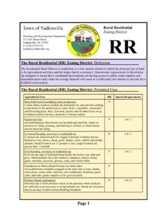
6 Buyer is responsible for all costs incurred in removal and re- Installation of product and must pre-pay shipment to factory or point of CanadaHeating Cable Warranty Union Street Elmira ON N3B 3L7T. (800) 794-3766 Power Cordset w/ Lighted PlugSensor WireSplice ConnectionProbe LeadsRoof De-Icing Cable ReceptacleMain HousingFig. 1 Kit also includes (6) clips and (2) mounting USAH eating Cable Warranty Dept. 2 Connectictut South Drive East Granby, CT 06026T. (800) 537-4732 2016 EASYHEAT 14053-001 Rev. 7RS2 Automatic Roof De-Icing Cable ControlInstallation and Operation InstructionsRS-2 HousingProbe LeadsReceptacleINSTALLATION INSTRUCTIONS1.
7 Mount the main housing under the soffit, or equivalent location protected from the weather, using the screws provided. Refer to Fig. 2. Ensure that the mounting location is close enough to the receptacle supplying power to the unit to allow the cord on the Control to be plugged in. The connection should be located for the best protection from the weather and a drip loop used as appropriate. Drip loops should be used between the Control box and both the sensor wire and power connection to the heater wire as appropriate for maximum protection. If desired, this receptacle can be controlled by a switch (with a pilot light) located inside the house. See Fig. Lay the Splice Connection and sensor wire along the bottom of the gutter within two inches of the roof De-Icing Cable . Route the sensor wire over at least one gutter support strap or nail in order to sense the full depth of the gutter, then route along one triangular weave of the heating Cable on the roof as per diagram.
8 At the peak of the second triangle, attach the sensor wire up the roof, at least 2 feet ( cm) past the heater wire as illustrated. Use the clips provided to secure the sensor wire to the roof. Gently squeeze the coated end of the clip around the sensor wire. See Fig. Connect the cord from the roof Cable to the Roof Sentry Control box. Cables up to a maximum of 1200 Watts can be Plug the Roof Sentry cord-set into the receptacle. Ensure that this connection remains If using a pilot light, turn the pilot light switch to the ON position. The pilot light on the plug of the unit will be Your Roof Sentry is now ready to Control the Cable on your The power light indicator (next to the receptacle on the Control box) will only be lit, when the roof De-Icing Cable is energized. Fig. For Roof without gutter- Lay the sensor wire along the triangular weave of the heating Cable as shown on Fig.
9 5 and secure the main housing under the eave of the roof as shown on Fig. The RS2 may be used on metal and membrane roofs. Typically Installation of the roof clips on these types of roofs requires an adhesive be used to bond the clip to metal or membrane material. The choice of adhesive is left to the installer. Care must be taken on metal roof installations to ensure the sensor wire is protected from sliding snow or ice, which could damage the sensor wire and render the RS2 inoperable. Prior to installing on a membrane roof ensure the sensor wire will be able to reach the area where melting is occuring, The RS2 sensor wire cannot be 2 Fig. 4 Power Light IndicatorOPERATION INSTRUCTIONSThe roof Control is designed to energize the roof De-Icing cables ONLY when roof snow/ice melting conditions exist AND there is a risk of this melt water refreezing at the roof edge to form an ice dam.
10 This ensures that ice dams will not form and that energy consumption is RS2 senses the ambient temperature. The sensor wire senses the presence of water. If the temperature is below about 4 C (40 F) AND at least 10 inches ( cm) of the sensor is laying in (or on) water, then the RS2 will apply power to the roof Cable . Note that snow or ice surrounding the sensor wire WILL NOT result in activation of the RS2 to energize the RS2 is provided with a Self Test function mode; when it is first energized or when it recovers from a power outage, the Power Indicator Light will turn on for 2 minutes if at least 10 inches of the sensor wire is submerged in water regardless of the ambient temperature. The Power Indicator Light will then turn off and the Self Test function will be completed. The RS2 will return to normal operation in about 25 the power to the RS2 during summer the beginning of the heating season and monthly during operation, inspect the RS2 Control and its connection to the electric power source.