Transcription of RS485 – JBUS/MODBUS - Mersen
1 Syst mes de Coupure et de ProtectionIndustrial Switching and Protection SystemsON1 COMFDINLGBEPSOCOMEC GROUP SWITCHING PROTECTION & UPSDIRIS A40/A41RS485 JBUS/MODBUS Operating instructions2 SOCOMEC - R f. : CDR 27 038_gb3 SOCOMEC - R f. : CDR 27 038_gbPRELIMINARY OPERATIONS _____4 GENERAL INFORMATION _____4 INSTALLATION _____5 CONNECTION _____5 PROGRAMMING _____6 COMMUNICATION ADDRESS _____7 COMMUNICATION SPEED _____7 COMMUNICATION PARITY_____8 COMMUNICATION STOP BIT _____8 COMMUNICATION _____9 THE STANDARD COMMUNICATIONS FRAME _____9 LIST OF PARAMETERS TO BE DISPLAYED _____10 Table of values with allocated current and voltage winf-ding ratios on 2 words_____10 Address available with the Monitoring or Control/Command option_____11 Instant value display _____12 Table of values without allocated current and voltage winding ratios on 1 word _____13 Alarm event log _____16 Table of current and voltage harmonics _____30 Option recognition table_____33 LIST OF PARAMETERS TO BE DISPLAYED OR PROGRAMMED _____34 RESET TO ZERO: ENERGY METERS AND MAX.
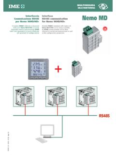
2 VALUES _____43 SAVED COMMAND _____44 PULSE METERS VALUES _____44 DATE AND HOUR SETTINGS _____45 LAST 10 ALARMS EVENT LOG _____45 LAST 10 VOLTAGE DIPS EVENT LOG / SAG _____59 LAST 10 VOLTAGE SURGE EVENT LOG / SWELL _____64 MINIMUM AND MAXIMUM INSTANTANEOUS VALUES _____69 LAST 10 VOLTAGE CUT-OFFS EVENT LOG / SAG _____73 MEAN POWER EVENT LOG _____75 MEAN VOLTAGE EVENT LOG _____75 MEAN FREQUENCY EVENT LOG _____75 TECHNICAL CHARACTERISTICS _____76 GLOSSARY OF ABBREVIATIONS _____76 ContentsGB4 SOCOMEC - R f. : CDR 27 038_gbDIRIS A40/A41- RS485 - JBUS/MODBUS PRELIMINARY OPERATIONSF unctionsThe optional IP Communication module must beconnected to the DIRIS A40/A41 (r f. : 4825 0A40,4825 0A41, 4825 1A40, 4525 1A41). It provides anRS485 serial link (2 or 3 wires) with JBUS/MODBUS protocol for the use of DIRIS A40/A41from a PC pointsFor a standard configuration, an RS 485 link is used toconnect up to 31 DIRISor COUNTIS Ciwith a PC ora PLC over a distance of 1200 metres, usingJBUS/MODBUS 1 N 2 N n R = 120 1200 MR = 120 ProgrammablecontrollersOther systemsN 1 R = 120 ProgrammablecontrollersOther systemsrepetorRS485 0+- -+0 N n R = 120 1200 M1200 MDIRIS 109 E GBDIRIS 110 E GBRecommendations:You should use a shielded twisted pair (LIYCY type).
3 Ina disturbed environment or large network (in terms oflength) we recommend the use of a shielded twistedpair (type LIYCY-CY). A repeater (1 channel) or an arrestor (4 channels)should be used if you intend to exceed the distance(1200 m) and/or maximum number (31) of contact us for more :A 120 ohm resistance (found on the additional module)must be fixed at both ends of the solutions are available (modem, optical fibre, etc.).Please contact personnel and product safety please read thecontents of these operating instructions carefullybefore the following points as soon as you receivethe DIRIS A40/A41package: the packing is in good condition, the product has not been damaged during transit, the product reference number conforms to yourorder, the package contains the product and the INFORMATION5 SOCOMEC - R f.
4 : CDR 27 038_gbGBDIRIS A40/A41- RS485 - JBUS/MODBUS CONNECTIONThe module is fitted onto the back of the DIRIS A40/A41in one of the 4 positions 342 ADIRIS 343 AON1ON10V - +R=120 DIRIS 347 A Fix the module in one of the four positions. Follow indications when connecting the on voltage A40/A41must be switched offINSTALLATION6 SOCOMEC - R f. : CDR 27 038_gbDIRIS A40/A41- RS485 - JBUS/MODBUS PROGRAMMINGP revious menuFollowing - R f. : CDR 27 038_gbGBDIRIS A40/A41- RS485 - JBUS/MODBUS PROGRAMMATIONCOMMUNICATION ADDRESS> Example : COM ADR = 7x 3x 2x 1confirmCOMMUNICATION SPEED> Example : BDS = 19 200 baudsx 1x 1x 1confirm8 SOCOMEC - R f. : CDR 27 038_gbDIRIS A40/A41- RS485 - JBUS/MODBUS PROGRAMMATIONCOMMUNICATION PARITY> Example : PAR = Evenx 1x 1 (Odd)x 2 (Even)x 3 (No)x 1confirmCOMMUNICATION STOP BIT> Example : STOP = 2x 1x 1 (2 bits)x 2 (1 bits)x 1confirm9 SOCOMEC - R f.
5 : CDR 27 038_gbGBDIRIS A40/A41- RS485 - JBUS/MODBUS COMMUNICATIONThe JBUS/MODBUS used by the DIRIS A40/A41involves a dialogue using a master-slave hierarchicalstructure. There are two possible dialogues: the master communicates with a slave (DIRIS) andwaits for its reply the master communicates with all the slaves (DIRIS)without waiting for their mode of communication is the RTU (RemoteTerminal Unit) using hexadecimal characters of at least8 to the JBUS/MODBUS protocol, transmissiontime must be less than 3 silences, the emission timeof 3 characters so that the message is processed bythe correctly use information, the following functions areimportant:3: to read n words (maximum 128).6: to write one : to diagnose exchanges between the master andthe slave via meters 1, 3, 4, 5 and : to write n words (maximum 128).NB:When selecting slave address 0, a message is sent toall the instruments present on the network (only forfunctions 6 and 16).
6 Comment :The response time (time out question/answer) is 250 msmaximum THE STANDARD COMMUNICATIONS FRAMES lave addressFunction codeAddressDataCRC 16 The standard communications frame consists of:10 SOCOMEC - R f. : CDR 27 038_gbDIRIS A40/A41- RS485 - JBUS/MODBUS COMMUNICATIONLIST OF PARAMETERS TO BE DISPLAYED (FUNCTION 3)Table of values with allocated current and voltage winf-ding ratios on 2 wordsDecimal TextUnitaddressaddressof words7683002 Phase 1 currentmA 7703022 Phase 2 current mA 7723042 Phase 3 current mA 7743062 Neutral current mA 7763082 Phase to phase voltage U12 V/100 77830A2 Phase to phase voltage U23 V/100 78030C2 Phase to phase voltage U31 V/100 78230E2 Phase to neutral voltage phase 1 V/100 7843102 Phase to neutral voltage phase 2 V/100 7863122 Phase to neutral voltage phase 3 V/100 7883142 FrequencyHz/100 7903162 active power +/-kW/100 7923182 reactive power +/-kvar/100 79431A2 apparent power kVA/100 79631C2 power factor : leading and +.
7 Lagging 79831E2 Active power phase 1 +/-kW/100 8003202 Active power phase 2 +/-kW/100 8023222 Active power phase 3 +/-kW/100 8043242 Reactive power phase 1 +/-kvar/100 8063262 Reactive power phase 2 +/-kvar/100 8083282 Reactive power phase 3 +/-kvar/100 81032A2 Apparent power phase 1 kVA/100 81232C2 Apparent power phase 2 kVA/100 81432E2 Apparent power phase 3 kVA/100 8163302 Power factor phase 1 -: leading and +: lagging factor phase 2 -: leading and +: lagging factor phase 3 -: leading and +: lagging I1mA 8243382avg I2mA 82633A2avg I3mA 82833C2avg active power +kW/100 83033E2avg active power -kW/100 8323402avg reactive power +kvar/100 8343422avg reactive power -kvar/100 8363442avg apparent powerkVA/100 8383462max/avg I1mA 8403482max/avg I2mA 84234A2max/avg I3mA 84434C2max/avg active power +kW/100 84634E2max/avg active power -kW/100 8483502max/avg reactive power +kvar/100 8503522max/avg reactive power -kvar/100 8523542max/avg apparent powerkVA/100 8543562hour meter 1/100 h 8563582 Active energy + kWh 85835A2 Reactive energy + kvarh 86035C2 Apparent energy kVAh 86235E2 Active energy -kWh 8643602 Reactive energy -kvarh 11 SOCOMEC - R f.
8 : CDR 27 038_gbGBDIRIS A40/A41- RS485 - JBUS/MODBUS COMMUNICATIONLIST OF PARAMETERS TO BE DISPLAYED (FUNCTION 3)Address available with the Monitoring or Control/Command optionDecimal TextUnitaddressaddressof words8663622 Input pulse meter 1 8683642 Input pulse meter 2 8703662 Number of impulse meters 8723682 Current alarm : 0 : no alarm 1 : I 2 : U 3: P+ 4: Q+ 5: S 6: F 7 : PFL 8 : thd I 9 : thd U 10 : In 11 : HOUr 12 : V 13 : thd In 14 : thd V 15 : P- 16 : Q- 17 : PFC 87436A2 Current overrun : 0 : no alarm 1 : I 2 : U 3: P+ 4: Q+ 5: S 6: F 7 : PFL 8 : thd I 9 : thd U 10 : In 11 : HOUr 12 : V 13 : thd In 14 : thd V 15 : P- 16 : Q- 17 : PFC 87636C2 Number of inputs-outputs -Low-order: number of inputsHigh-order: number of outputs 87836E2 Status of inputs-outputs 0 : status input 1 (0 = open, 1 = closed) bit 1 : status input 2 (0 = open, 1 = closed) bit 2 : status input 3 (0 = open, 1 = closed) bit 3 : status input 4 (0 = open, 1 = closed) bit 4 : status input 5 (0 = open, 1 = closed) bit 5 : status input 6 (0 = open, 1 = closed) bit 16 : status output 1 (0 = open, 1 = closed) bit 17 : status output 2 (0 = open, 1 = closed) bit 18 : status output 3 (0 = open, 1 = closed) bit 19 : status output 4 (0 = open, 1 = closed) bit 20 : status output 5 (0 = open, 1 = closed) bit 21 : status output 6 (0 = open, 1 = closed)12 SOCOMEC - R f.
9 : CDR 27 038_gbDIRIS A40/A41- RS485 - JBUS/MODBUS COMMUNICATIOND ecimal TextUnitaddressaddressof words8803702 System value for current mA 8823722 System value for phase-to-phase voltage V/100 8843742 System value for phase-to-neutral voltage V/100 8863762avg U12V/100 8883782avg U23V/100 89037A2avg U31V/100 89237C2avg V1V/100 89437E2avg V2V/100 8963802avg V3V/100 8983822avg FHz/100 9003842max/avg U12V/100 9023862max/avg U23V/100 9043882max/avg U31V/100 90638A2max/avg V1V/100 90838C2max/avg V2V/100 91038E2max/avg V3V/100 9123902max/avg FHz/100 9143922avg InmA 9163942max/avg InmA 9183962 Mean positive active power between 2 kW9203982 Mean negative active power between 2 kW92239A2 Mean positive reactive power between 2 kvar92439C2 Mean negative reactive power between 2 kvarLIST OF PARAMETERS TO BE DISPLAYED (FUNCTION 3)Instant value display Example:To display all the values for DIRIS number 5 in oneinquiry, the following frame should be sent:Zone size: 158 words (decimal) or 9E (hexadecimal).
10 Slave05 Function03 High-orderaddress03 Low-orderaddress00 High-order word n 00 Low-order word n 9 ECRC 16C5A713 SOCOMEC - R f. : CDR 27 038_gbGBDIRIS A40/A41- RS485 - JBUS/MODBUS COMMUNICATIONLIST OF PARAMETERS TO BE DISPLAYED (FUNCTION 3)Table of values without allocated current and voltage winding ratios on 1 wordDecimal TextUnitaddressaddressof words17927001 Phase 1 currentmA 17937011 Phase 2 current mA 17947021 Phase 3 current mA 17957031 Neutral current mA 17967041 Phase to phase voltage U12 V/10 17977051 Phase to phase voltage U23 V/10 17987061 Phase to phase voltage U31 V/10 17997071 Phase to neutral voltage phase 1 V/10 18007081 Phase to neutral voltage phase 2 V/10 18017091 Phase to neutral voltage phase 3 V/10 180270A1 FrequencyHz/100 180370B1 active power +/-W 180470C1 reactive power +/-var180570D1 apparent power +/-kVA180670E1 power factor L/C -: leading and +.