Transcription of RTD CALIBRATOR MODEL 211
1 ALTEK INDUSTRIES CORP35 Vantage Point DriveRochester, New York 14624 (716) 349-3500 Fax: (716) 349-3510E-Mail: DATA SHEETA TRANSMATION COMPANYGENERAL DESCRIPTIONRTD CALIBRATORMODEL 211211 Additional RTD Simulators: See Data Sheet 11 8 RTD TYPES & OHMSS elect Pt, Cu, or Ni TEMPERATURE INPUT & OUTPUTD irectly in degrees QUIK CHEK SWITCHT hree Points, HI, LO, & Set ACCURACY,1 OR RESOLUTIONF ield Selectable F or C THREE YEAR WARRANTYT oolbox tough CUSTOM RANGES AVAILABLEA ltek s MODEL 211 RTD CALIBRATOR lets you SIMULATE and READRTDs over the entire industrial temperature range. Use withtransmitters, recorders, controllers, alarms, indicators, dataacquisition and computer systems. Switch between four Platinum100, one Pt 1000, one Cu 10, two Ni RTD curves or OHMs rangesfrom to and to customize the MODEL 211 to lock-in 1 resolution, fixed C or F or front selectable F/ C operation.
2 Read and simulate2-Wire and automatically compensate for 3-Wire RTDs with built-in leads. A plug-in lead is supplied for 4-Wire RTD MODEL 211 turns on in the RTD type last used. Other RTDtypes may be selected each time the unit is turned on. If youalways use one RTD curve, lock-in the selected RTD type with theinternal DI P switch to prevent accidental change to an unwantedRTD type. SIMULATE MODE ACTS LIKE AN RTD SENSORR esolution is over the full range for Platinum 100 ohm RTDsimulation, with 1 mA current supplied from the external range, at 1 mA current, provides resolution from and autoranges to resolution from to (See graph for other excitation currents). QUIK-CHEK function stores THREE output temperatures for realconvenience. The ALTEK MODEL 211 simulates key temperaturesfor repetitive calibrations.
3 Turn the knob to check trip points, control-ler action or hysteresis. The fast response 211 sets quickly withoutovershoot. Memory is retained even when power is MODEL 211 has a unique circuit which lets you simulate RTD swith most transmitters, recorders and other RTD inputs with fixed orintermittent excitation currents. READ MODE MEASURES RTDs DIRECTLYThe MODEL 211 display gives you fast, accurate temperaturemeasurement with and 1 degree or with and ohmresolution. Two, three and four wire hookups assure accuracy inlong cable runs. Open RTDs and leads are detected and indicatedon the LCD display. Two readings per second track fast movingtemperatures. MAX and MIN memories are continuously updated fromturn-on or whenever the RESET button is pressed. MODEL 211gives you a handy tool to monitor temperatures for drift or controldeviation.
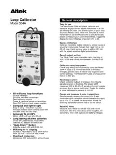
4 Just flip the QUIK-CHEK switch to display the MlNimumand MAXimum temperature measured since SEQUENCEEach time the MODEL 211 is turned on, the LCD displays allsegments for 1 second. It then displays the sensor material andAlpha (ohms at 100 C/ohms at 0 C) for the currently selectedRTD type for approximately 3 seconds. Any of 8 built-in RTD typesand alpha values plus ohms may be selected during the RTDturn-on RANGESC ustom ranges for additional RTD types, Dew Cell or other resistivesensors are also available. The Metal, Base Resistance and Alphavalue for the custom RTD curve must be specified. Adding a customrange to a 211 may require removing one of the standard otherwise specified the Ni 110 (Bristol 7 NA) will be replacedwith the custom range if INSTRUCTIONSALTEK INDUSTRIES CORPR ochester, New York 14624 IN OFFHI F CONMA XLOMI N12 RTD CALIBRATORALTEK MODEL 211 SIMULATEREADHISETLOMAXREADMINSTORERESETQ UIK-CHEKALTEK INDUSTRIES CORPROCHESTER 14623 USASIMOVER UNDERSETTING OPERATING MODE (DIP SWITCHES)SELECTING F OR CThe MODEL 211 may be internally configured in one ofthree modes.
5 The first two modes are for full-time use in F or full-time use in C. The third mode allows front panelselection of F or C each time the unit is turned on. Ifyour facility is completely in F or C, set the internal DIPswitches of the 211 to operate as a dedicated F or Cinstrument (see Setting Operating Mode below).USING F/C MODEIn F/C mode the temperature scale isselected by setting the QUIK-CHEK switch before turning the unit on. Place theswitch to HI/MAX to select F or LO/MIN toselect C. If the unit is turned on with theswitch in the SET/READ (center) positionthe temperature scale most recently usedwill be : The MODEL 211 will automaticallyconvert the temperatures in memorybetween F and C. For example, if 212 Fis stored in HI and the MODEL 211 is switchedto C, 100 C will be AUTORANGING OR 1 RESOLUTIONThe MODEL 211 may be internally configuredto autorange or to constantly display withfixed resolution.
6 When autoranging isselected, the MODEL 211 will displaytemperatures with or 1 and ohms or resolution. When fixed rangeis selected, the MODEL 211 will display temperatures with 1 and ohms with : Some ranges are always displayedwith 1 RANGE/UNDER RANGEOut-of-range temperatures are indicated by- - - - - and OVER or UNDER on the displayduring READ mode. If this occurs check forproper connections and RTD type selec-tion. During SIMULATE mode excitationcurrents below are indicated bythe word SIM flashing on the currents above are indi-cated by - - - - - and SIM flashing on thedisplay. Check for proper BATTERYLow battery is indicated by BAT on the LCDdisplay. Approximately 10 hours of opera-tion remain before the LCD goes blank andthe MODEL 211 shuts itself down.
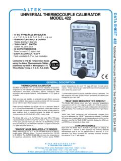
7 Turn theModel 211 off. Remove the four cornerscrews and lift the unit out of the case. Thebattery is fastened to the bottom printedcircuit board and is easily : If the new battery is installed within 30seconds of removing the old battery the QUIK-CHEK values will remain in CALIBRATORALTEK MODEL 211 SIMULATEREADHISETLOMAXREADMINSTORERESETQ UIK-CHEKALTEK INDUSTRIES CORPROCHESTER 14623 USA9 VoltCONNECTIONSThe MODEL 211 accurately simulates and reads 2, 3, or4 wire RTDs. It has three leads permanently attachedand a socket for a fourth wire (supplied). The LCDindicates 4-WIRE when the fourth wire is fourth wire must only be plugged in when simulatingor reading 4-Wire RTDs. All connecting wires must bethe same length and of the same material running alongthe same path to insure maximum , THREE OR FOUR WIRETwo wire RTD measurements are less accurate thanother RTD measurements because of the errorsintroduced by the resistance of the lead wires.
8 The thirdwire in a three wire hookup provides the instrumenta-tion with a reference connection for the lead wires. Themeasuring instrumentation uses this reference to inferthe actual resistance of the RTD element without theleads. Four wire RTD measurements take into accountall wires other than the RTD sensing makes four wire RTDs best suited for RTD TYPESE ight RTD types or ohms may be selected each timethe MODEL 211 is turned on. An internal DIP switch maybe used to disable the front panel selection to perma-nently lock in a single RTD type (see below).To change RTD types:1) Press & hold the STORE pushbutton while switchingthe unit on or while = is blinking during the first 3seconds after the unit is turned ) Continue to hold the STORE pushbutton. The LCDwill scroll through the 8 RTD types and ohms, display-ing the Sensor material and value for each RTD ) Release the STORE pushbutton when the desiredMetal and value are ) After 2 seconds, the MODEL 211 will store the RTD typeyou selected and will begin Simulating or ReadingRTD ) Each additional time the MODEL 211 is turned onwithout holding the STORE pushbutton, the newlyselected RTD type will be displayed and used.
9 If anincorrect type is selected, repeat steps I through : For Pt 100 ohm, = the word DIN willappear on the WITH INTERMITTENT EXCITATION CURRENTSSome transmitters, recorders and other RTD inputdevices use intermittent, or pulsed, excitation currentsto measure the resistance of the RTD. The MODEL 211may be internally configured to operate with both fixedexcitation currents (default operation) and with inter-mittent currents (see Setting Operating Mode below). 100 = *Factory Settings(All Switches Down)2 Factory Settings-AllOther RTDType2 SelectableRTD Types*5 Fixed CurrentOnly*5 Fixed & IntermittentCurrents1) Turn the MODEL 211 OFF2) Remove the 4 corner screws and lift faceplate assembly out of the ) Set the DIP switches for your options as diagrammed : C/ F selection is the default for shipments in the , C for all other between autoranging /1 ( ) and fixed 1 ( ).
10 FIXED RTD TYPES witches between a single RTD type andRTD type selection at turn SCALES witches between fixed F, fixed C or C/ F selection at turn CURRENTS witches between simulating with fixed excitationcurrents and excitation current selection at turn C234 C/ FSwitchable*3434 Fixed F(SwitchUp)1(SwitchDown)1 Fixed 1 ( )Autoranging*OPERATING INSTRUCTIONSSIMULATE MODE (RESISTANCE OUTPUT OR RTD TEMPERATURE EQUIVALENT)make sure that the excitation current is in the range of : Some smart transmitters and scanning recorders or indicatorsuse intermittent currents to measure RTD s. Try puttingrecorders into a calibrate mode or lock them into one MODEL 211 can be configured to accept intermittentexcitation with mininum 125 msec fixed current at a mininumrepetition rate of 1/sec (see OPERATING WITH INTERMIT-TENT EXCITATION CURRENTS).