Transcription of SAE Engine Mount - Berkeley Pumps
1 SectionSAE Tech Data 4117 Page1 DateJanuary 1, 2013 Supersedes 9-1-11 Type B centrifugal PumpsClose coupled pump endsSAE Engine MountSelection For Pumping ApplicationPump EndWhen delivering the required capacity (GPM) to the system piping, the pump must add the amount of Head required by the system at that capacity. The operating head-capacity point should be as close as possible to the highest efficiency line shown on the performance curve, and MUST be below the head-capacity line labeled Maximum RPM. The maximum operating RPM for the pump is determined by bearing life, or in some cases, by the pressure limits of the pump.
2 The maximum working pressure for NPT tapped and flanged Pumps , per ANSI class 125, is 175 PSI unless otherwise stated on the pump curve. When used as a booster pump, the pressure at the pump discharge (combination of inlet pressure plus pressure added by the pump) must not exceed the maximum working pressure shown. The Suction NPSHA must be greater than the NPSHR shown on the pump Engine used to drive the pump must be suitable for the application. It must produce adequate power for the pump demand, and must rotate in the correct direction (standard rotation is CLOCKWISE when viewed from the front of Engine ).
3 Internal Combustion Engines are variable speed and variable power machines. The power output depends upon the Engine speed (RPM) and will be reduced when operating altitude, and/or the air temperature increases. When driving the pump at the RPM required to deliver water into the system piping, the Engine must operate within the Engine manufacturers minimum and maximum RPM limits. The power output to supply the pump power demand must not exceed the CONTINUOUS POWER RATING of the Engine , after derating for all power consuming Engine accessories, and adjustment for installation site altitude and air temperature.
4 Proper power matching of the pump and Engine is the responsibility of the pump and Engine unit Pump End To Bracket SizeType B Engine drive Pumps are available to fit engines having a standard 5 through 1 flywheel a new Engine , the Engine supplier can provide the housing an existing Engine , the flywheel housing bore and bolt circle can be measured and compared against the standard S. A. E. housing dimensions listed in Table I, to identify the housing S. A. E. IFlywheel Housing Flywheel Housing Size12345A20-1/817-5/816-1/814-1/412-3/8 B20-7/818-3/816-7/81513-1 1 ENGINE1850 0695 ABC 2013 B1621 (01/14/13)SectionSAE Tech Data 4117 Page2 DateJanuary 1, 2013 Supersedes 9-1-11 Type B centrifugal PumpsClose coupled pump endsSAE Engine Mount Measure the flywheel housing bore (A), and the bolt circle (B), as accurately as possible with a tape measure (to the nearest 1/32 inch).
5 Count the number of threaded holes in the flywheel housing (C). Test the threaded holes with a bolt, to determine the thread series. Unified National Coarse (UNC) cap screws are furnished with the pump end. If the hole threads are other than UNC, the assembler must substitute the correct bolts. Compare the measured dimensions (A), (B), and (C) against Table I, to determine the S. A. E. number of the flywheel housing, and select the pump end to fit this housing. If the dimensions do not match the S. A. E. standard dimensions in table 1, then the housing is not an S.
6 A. E. standard size. The close-coupled pump end cannot be used with the housing. A frame-mounted pump with a flexible coupling can be used. Record measurements on the dimension form on Page 7 in the spaces provided under Flywheel Housing CouplingThe flywheel coupling transmits power from the Engine flywheel to the pump shaft. The maximum power that a coupling can safely handle is shown by a rating number, R , which is listed in the coupling dimensions When selecting a flywheel coupling for a pump and Engine , first determine the power rating that the pump will demand.
7 On the pump performance curve, find the RPM and BHP values required to produce the application head-capacity Divide the BHP by the RPM, then multiply the result times 100. The result will be the demand number for the pump. For example, a B6 JQBM can deliver 1500 GPM at 260 feet Total Head when running at 2200 RPM. The power required by the pump will be 120 BHP. The demand number will be:(120/2200) x 100 = Next, select a coupling that can safely transmit the power, and which will fit the flywheel dimensions. For a coupling to be suitable, it must have an R rating number GREATER THAN the pump demand number.
8 In the above example, the minimum coupling R number would be : The elastomer disk design of Berkeley flywheel couplings provides smooth power flow from the Engine to the pump, which minimizes torsional vibration the broad range of engines available, a torsional mismatch can occur, which can cause excessive stress in the pump shaft and compatibility of the Engine , pump, and coupling is the responsibility of the assembler. Berkeley Pumps will supply data for the pump and coupling for use by the assembler for a torsional.
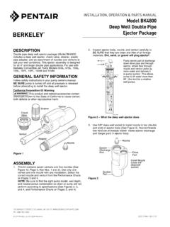
9 If the flywheel is fitted with a pilot bearing pressed into a bore at the center, remove it to avoid interference with the pump For Industrial Type Over-Center ClutchesFigure 2 shows the hollowed-out appearance of the flywheels made for use with over-center type clutch power take-off flywheels will have a recessed bore machined into the face, and a set of tapped holes, which will be used to attach the coupling to the are governed by SAE standard J620d, and are listed in Tables IIA and IIB. The Clutch Size shown in the table is the nominal clutch facing diameter for drive ring type over-center Tech Data 4117 Page3 DateJanuary 1, 2013 Supersedes 9-1-11 Type B centrifugal PumpsClose coupled pump endsSAE Engine MountFor a new Engine , the Engine supplier can furnish the an existing Engine , measure the flywheel dimensions, D through H , using a tape measure and a machinists combination square.
10 Measurements to the nearest 1/32 will usually be dimensions match a standard flywheel coupling listed in Tables IIA or IIB, select the one that has an R rating number greater than the pump demand number. Record measurements on the dimension form on Page 6 in the spaces provided under Flywheel IIA Wide RPM Range, Elastomer Mounted HubClutch SizeFlywheel DimensionsFlywheel CouplingDEBCFGHRC atalog NumberShaft Spline (UNC)6-1/2 65/16-188-1/2 10T6-1/2 65/16-188-1/2" 10T7-1/2 85/16-189-1/2 10T7-1/2 85/16-189-1/2 10T8 63/8-1610-3/8 10T8 63/8-1610-3/8 10T10 83/8-1612-3/8 10T10 83/8-1612-3/8 10T11-1/2 83/8-1613-7/8 10T11-1/2 83/8-1613-7/8 10 TTable IIB Heavy Duty, Elastomer Mounted HubClutch SizeFlywheel DimensionsFlywheel CouplingDEBCFGHRC atalog NumberShaft Spline (UNC)