Transcription of Safty-door Switch D4NS - Mouser Electronics
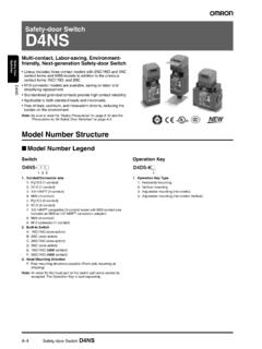
1 Safty-door SwitchD4 NSMulti-contact, Labor-saving, Environment-friendly, Next-generation safety -door Switch Lineup includes three contact models with 2NC/1NO and 3NC contact forms and MBB models in addition to the previous contact forms 1NC/1NO, and 2NC. M12-connector models are available, saving on labor and simplifying replacement. Standardized gold-clad contacts provide high contact to both standard loads and Number StructureModel Number LegendSwitch1. Conduit/Connector size1 (1-conduit)2:G1/2 (1-conduit)3:1/2-14 NPT (1-conduit)4:M20 (1-conduit)5 (2-conduit)6:G1/2 (2-conduit)7:1/2-14 NPT compatible (2-conduit model with M20 conduit size includes an M20-to-1/2-14 NPT conversion adapter)8:M20 (2-conduit)9:M12 connector (1-conduit)2. Built-in SwitchA:1NC/1NO (slow-action)B:2NC (slow-action)C:2NC/1NO (slow-action)D:3NC (slow-action)E:1NC/1NO (MBB contact)F:2NC/1NO (MBB contact)3. Head Mounting DirectionF:Four mounting directions possible (Front-side mounting at shipping)Note:An order for the head part or the Switch part alone cannot be accepted.
2 (The Operation Key is sold separately.)Operation Key1. Operation Key Type1:Horizontal mounting2:Vertical mounting3:Adjustable mounting (Horizontal)5:Adjustable mounting (Horizontal/Vertical)Be sure to read the safety Precautions on page 10 and the Precautions for All safety Door Switches .123D4NS-@@@ OMRON Corporation 2008 All Rights Reserved. D4 NSOrdering InformationSwitches (Operation Keys are sold separately.)Note: recommended models for equipment and machinery being exported to Europe are those with an M20 or conduit sizes, and for North America, the recommended models are those with a 1/2-14 NPT conduit sizes. is used as the material for the d4ns housing and head. Use the metal D4BS safety -door Switch for applications requiring greater mechanical strength. * Models with Korean S-mark configurationConduit opening/ConnectorModel1-ConduitSlow-acti on1 *G1/2D4NS-2AF *1 *G1/2D4NS-2BF *1/2-14 NPTD4NS-3 BFM20D4NS-4BF2 *G1/2D4NS-2CF *1 *G1/2D4NS-2DF *1/2-14 NPTD4NS-3 DFM20D4NS-4 DFSlow-action MBB contact1 , includes M20-to-1/2-14 NPT conversion , includes M20-to-1/2-14 NPT conversion adapterD4NS-7 BFM20D4NS-8BF2 , includes M20-to-1/2-14 NPT conversion , includes M20-to-1/2-14 NPT conversion adapterD4NS-7 DFM20D4NS-8 DFSlow-action MBB contact1 , includes M20-to-1/2-14 NPT conversion adapterD4NS-7 EFM20D4NS-8EF2 , includes M20-to-1/2-14 NPT conversion adapterD4NS-7 FFM20D4NS-8FF1-Conduit, with connectorSlow-action1NC/1 NOM12 connectorD4NS-9AF2 NCD4NS-9 BFSlow-action MBB contact1NC/1 NOD4NS-9EF: Models with certified direct opening (c)Copyright OMRON Corporation 2008 All Rights Reserved.
3 D4 NSOperation KeysSpecificationsStandards and EC DirectivesConforms to the following EC Directives:xMachinery DirectivexLow Voltage DirectivexEN50047xEN60204-1xEN1088xGS-ET -15 Certified Standards*1. Certification for CSA No. 14 is authorized by the UL mark.*2. Only certain models have been Standard RatingsT V (EN60947-5-1), CCC ( )Note:Use a 10 A fuse type gI or gG that conforms to IEC60269 as a short-circuit protection device. This fuse is not built into the (UL508, CSA No. 14)A300Q300 TypeModelD4DS-K1D4DS-K2D4DS-K3D4DS-K5 Horizontal mountingVertical mountingAdjustable mounting (Horizontal)Adjustable mounting (Horizontal/Vertical)Certification bodyStandardFile V Product ServiceEN60947-5-1 (certified direct opening)Consult yourOMRON representative for *1UL508, CSA (CCC) *2EN60947-5-12005-197 ItemUtilizationcategoryAC-15DC-13 Rated operating current (Ie)3 ARated operating voltage (Ue)240 V250 VRated voltageCarry currentCurrent (A)Volt-amperes (VA)MakeBreakMakeBreak120 VAC10 A6067,200720240 VAC303 Rated voltageCarry currentCurrent (A)Volt-amperes (VA)MakeBreakMakeBreak125 (c)Copyright OMRON Corporation 2008 All Rights Reserved.
4 D4 NSCharacteristicsNote: above values are initial Switch contacts can be used with either standard loads or microloads. Once the contacts have been used to Switch a load, however, they cannot be used to Switch smaller loads. The contact surfaces will become rough once they have been used and contact reliability for smaller loads may be reduced. *1. The degree of protection is tested using the method specified by the standard (EN60947-5-1). Confirm that sealing properties are sufficient for the operating conditions and environment beforehand. Although the Switch box is protected from dust or water penetration, do not use the d4ns in places where foreign material may enter through the key hole on the head, otherwise Switch damage or malfunctioning may occur.*2. The durability is for an ambient temperature of 5 to 35qC and an ambient humidity of 40% to 70%. For more details, consult your OMRON representative.
5 *3. Do not pass the 3 A, 250 VAC load through more than 2 circuits.*4. These figures are minimum requirements for safe operation.*5. This value will vary with the switching frequency, environment, and reliability level. Confirm that correct operation is possible with the actual load of protection *1IP67 (EN60947-5-1)Durability *2 Mechanical1,000,000 operations ,000 operations min. (3 A resistive load at 250 VAC) *3300,000 operations min. (10 A resistive load at 250 VAC)Operating to m/sOperating frequency30 operations/minute opening force *460 N opening travel *410 mm resistance25 m: applicable load *51 mA resistive load at 5 VDC (N-level reference value)Rated insulation voltage (Ui)300 VRated frequency50/60 HzProtection against electric shockClass II (double insulation)Pollution degree (operating environment)3 (EN60947-5-1)Impulse withstand voltage (EN60947-5-1)Between terminals of same kVBetween terminals of different polarity4 kVBetween each terminal and non-current carrying metallic parts6 kVInsulation resistance100 M.
6 Gap2 u 2 mm resistanceMalfunction10 to 55 Hz, mm single amplitudeShock resistanceDestruction1,000 m/s2 m/s2 short-circuit current100 A (EN60947-5-1)Conventional free air thermal current (Ith)10 A (EN60947-5-1)Ambient operating temperature 30 to 70qC (with no icing)Ambient operating humidity95% 96 g ( d4ns -1CF) (c)Copyright OMRON Corporation 2008 All Rights Reserved. D4 NSStructure and NomenclatureStructureContact FormDiagrams Show State with Key Inserted.* MBB (Make Before Break) contacts have an overlapping structure, so that before the normally closed contact (NC) opens, the normally open contact (NO) formOperating patternRemarksD4NS-@A@1NC/1 NOD4NS-@B@2 NCD4NS-@C@2NC/1 NOD4NS-@D@3 NCD4NS-@E@1NC/1NO MBB * d4ns -@F@2NC/1NO MBB *Terminal 12 Terminal 32 (34)Terminal 31 (33)Terminal 32 (34)Terminal 31 (33)Terminal 22 Terminal 12 Terminal 21 Terminal 11 Terminal 11 Note: The 2-conduit models have the same terminal key holeHeadThe head can be mounted in four directions.
7 Sealing propertiesThe Switch casing ensures IP67 d4ns -@C@, d4ns -@D@, d4ns -@F@ d4ns -@A@, d4ns -@B@, d4ns -@E@11Zb33123411-1233-34 ONExtraction completionpositionOperation Key insertioncompletionpositionStrokeOnly NC contacts 11-12 have a certified direct opening terminals 11-12 and 33-34 can be used as unlike completionpositionOperation Key insertioncompletionpositionStrokeOnly NC contacts 11-12 and 31-32 have a certified direct opening terminals 11-12 and 31-32 can be used as unlike completionpositionOperation Key insertioncompletionpositionStrokeOnly NC contacts 11-12 and 21-22 have a certified direct opening terminals 11-12, 21-22, and 33-34 can be used as unlike completionpositionOperation Key insertioncompletionpositionStrokeOnly NC contacts 11-12, 21-22, and 31-32 have a certified direct opening terminals 11-12, 21-22, and 31-32 can be used as unlike completionpositionOperation Key insertioncompletionpositionStrokeOnly NC contacts 11-12 have a certified direct opening terminals 11-12 and 33-34 can be used as unlike completionpositionOperation Key insertioncompletionpositionStrokeOnly NC contacts 11-12 and 21-22 have a certified direct opening terminals 11-12, 21-22 and 33-34 can be used as unlike (c)Copyright OMRON Corporation 2008 All Rights Reserved.
8 D4 NSDimensions(Unit: mm)Dimensions and Operating Characteristics1-Conduit Models2-Conduit Models1-Conduit Connector ModelsNote: otherwise specified, a tolerance of mm applies to all are fluctuations in the contact ON/OFF timing for Switches with multiple poles (2NC, 2NC/1NO, or 3NC). Confirm performance before application. cap22 @FD4NS-2@FD4NS-3@ mounting holes0Tw o, 4+ dia. holes depth: 515 N N 3 mm(28 mm)60 N mm @FD4NS-2@FD4NS-3@FD4NS-4@FOperatingchara cteristicsKey insertion forceKey extraction forcePretravel (PT)Total travel (TT)Direct opening force*Direct opening stroke** Always maintain the above operating characteristics for safe @FD4NS-6@FD4NS-7@ mounting holes0Tw o, 4+ dia. holes depth: 515 N N 3 mm(28 mm)60 N mm @FD4NS-6@FD4NS-7@FD4NS-8@FOperatingchara cteristicsKey insertion forceKey extraction forcePretravel (PT)Total travel (TT)Direct opening force*Direct opening stroke** Always maintain the above operating characteristics for safe capModel31M12 13022 (14) mounting holes0Tw o, 4+ dia.
9 Holes depth: 515 N N 3 mm(28 mm)60 N mm @FOperatingcharacteristicsKey insertion forceKey extraction forcePretravel (PT)Total travel (TT)Direct opening force*Direct opening stroke** Always maintain the above operating characteristics for safe (c)Copyright OMRON Corporation 2008 All Rights Reserved. D4 NSOperation KeysNote:Unless otherwise specified, a tolerance of mm applies to all , 1328D4DS-K3 Black9 adjustment , 18 Holes(Enlargement)81715 Angleadjustment (7) (c)Copyright OMRON Corporation 2008 All Rights Reserved. D4 NSWith Operation Key Inserted (Relationship between Insertion Radius and Key Hole)Note:Unless otherwise specified, a tolerance of mm applies to all dimensions.( )( )(15)( )RedBlackD4NS-1@F + D4DS-K1(with Front-inserted Operation Key)44 to insertion faceHorizontal key insertion radius R 200 Permissible difference in center lines between the Operation Key and key hole is to insertion faceVertical key insertion radius R 200 Permissible difference in center lines between the Operation Key and key hole is permissible differencein center lines betweenthe Operation Keyand key hole is key insertionradius R 200 Vertical key insertion radius R to Keyinsertion to Keyinsertion faceD4NS-1@F + D4DS-K1(with Top-inserted Operation Key)The permissible differencein center lines betweenthe Operation Keyand key hole is 1.
10 (41)(8)(41)(15)( )(15)( )( )( )RedBlackD4NS-1@F + D4DS-K2(with Front-inserted Operation Key)40 to insertion facePermissible difference in center lines between the Operation Key and key hole is to insertion facePermissible difference in center lines between the Operation Key and key hole is key insertion radius R 200 Vertical key insertion radius R 200 RedBlackThe permissible differencein center lines betweenthe Operation Keyand key hole is key insertionradius R 200 Vertical key insertion radius R to Keyinsertion to Keyinsertion faceD4NS-1@F + D4DS-K2(with Top-inserted Operation Key)The permissible differencein center lines betweenthe Operation Keyand key hole is 1.(41)(8)(6)(41)(15) (c)Copyright OMRON Corporation 2008 All Rights Reserved. D4 NSNote:Unless otherwise specified, a tolerance of mm applies to all dimensions.(40 )( )( )( )RedBlackD4NS-1@F + D4DS-K3(with Front-inserted Operation Key)45 to insertion facePermissible difference in center lines between the Operation Key and key hole is to insertion facePermissible difference in center lines between the Operation Key and key hole is key insertion radius R 50 Vertical key insertion radius R 200 RedBlackThe permissible differencein center lines betweenthe Operation Keyand key hole is key insertionradius R 50 Horizontal key insertionradius R to Keyinsertion to Keyinsertion faceD4NS-1@F + D4DS-K3(with Top-inserted Operation Key)The permissible differencein center lines betweenthe Operation Keyand key hole is 1.