Transcription of SANI-FLOW RTD INSTRUCTIONS - Sanitary Instrumentation
1 Quality Products Since to place in a location where the RTD will be the least subjected to physical abuse. Wet locations are acceptable so long as the connector or cap is attached to the RTD during exposure to moisture or during wash down. For installation of a new RTD follow the wir-ing INSTRUCTIONS below. For replacement of an existing CSE RTD, simply install on line then attach the existing cable. No re-wiring or special tools are make sure that the connector is clean and dry before connecting. Never use pliers or other tools to tighten the connector; finger tighten REQUIREMENTSThe RTD has a standard 12mm Micro DC male receptacle which is widely accepted in all industries. The contacts are gold plated and have either 3 pins (single element RTD) or 6 pins (dual element RTD). The cable should be of Polyurethane construction, 22 gauge with 3 conductors (for a single element RTD) or 6 conductors (for a dual element RTD), IP67 rated and the contacts should be gold plated.
2 The connectors and cables should be shielded to prevent any RFI or EMI interference. The cable can be purchased from CSE or from most industrial supply warehouses. We also supply cabling accessories such as extra cable, field wireable con-nectors, and panel mount connectors; please refer to our Electronic Sensors Cable CSE RTDs (Resistance Temperature Detectors) have been specially designed for critical temperature measurement in Sanitary (and non- Sanitary ) fluid processing. We use a Pt-100 ( platinum 100 Ohm) 3-wire thin-film RTD which is encapsulated in an all stainless steel probe specifically designed to ensure the fastest response characteristics possible. The RTDs are combined with a standard 12mm industrial micro DC male receptacle with gold plated contacts to allow for quick and easy installation and removal. No bulky, complicated, leaking wiring heads or tools required, simply plug in the connector and go.
3 The electrical connection is IP67 rated which means that the RTDs can be aggressively washed down or temporarily submerged in water while in RTD signal should be connected to receiver such as a digital indicator, electronic recorder or PLC. The 3rd wire in a CSE RTD is used to compensate for the resistance added by the length of the wires. This allows for maximum cable lengths up to 200 feet. If longer cable lengths are required then it is best to use a temperature transmitter which converts temperature into a current output or digital : 3-Wire Pt-100 ( platinum 100 Ohm resistor) Coefficient: Alpha = Ohms/Ohm/Degree C (Per DIN EN 60751 according to IEC 751)Accuracy: C ( F)Stability: max. R0-drift after 1000h at 500 C)Element Range: -125 C to 200 C (-193 F to 392 F)Material: 316L SS wetted surfacesSurface Finish: Ramax = 8 micro-inchesRatings: 3-A, IP67 Ambient Temp.
4 Range: -50 C to 125 C (-58 F to 257 F)Connector: Std. 12mm industrial connector, Gold plated copper contacts and Polyamide insertCIP/SIP: YesAutoclavable: YesRTD INSTRUCTIONS1 1(+) BROWN 3(-) BLUE 4(-) BLACK 1(+) BROWN 2(-) WHITE 3(-) BLUE 4(+) BLACK 5(-) GRAY 6(-) PINK 2 4 3 1 4 3 5 6 32 PIN#1234 COLORB rownNo WireBlueBlackPIN#123456 COLORB rownWhiteBlueBlackGrayPinkWIRE TYPES ignal - RTD#1 Common - RTD#1 Common - RTD#1 Signal - RTD#2 Common - RTD#2 Common - RTD#2 WIRE TYPES ignal CommonCommonWIRINGS ingle Element RTD (3 Wires)CSE uses a 3-wire platinum thin film RTD (Pt-100). CSE cable utilizes the Brown as the signal wire and the Blue and Black as common wires. The shielding should be connected to earth ground at the receiver Element RTD (6 Wires)For a dual element RTD, CSE uses two 3-wire platinum thin film RTDs (Pt-100).
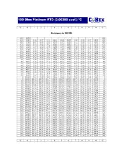
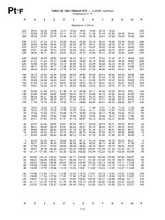
5 For the primary RTD CSE cable utilizes the Brown as the signal wire and the White and Blue as common wires. For the secondary RTD CSE cable utilizes the Black as the signal wire and the Gray and Pink as common wires. The shielding should be connected to earth ground at the receiver end. C 0 -1 -2 -3 -4 -5 -6 -7 -8 -9 -10 C -60 -60 -50 -50 -40
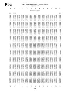
6 -40 -30 -30 -20 -20 -10 -10 0 0 C 0 -1 -2 -3 -4 -5 -6 -7 -8 -9 -10 C C 0 1 2 3 4 5 6 7 8 9 10 C 0 0 10 10 20 20 30 30 40
7 40 50 50 60 60 70 70 80 80 90 90 100 100 110 110 120 120 130 130 140 140 150 150 160 160 C 0 1 2 3 4 5 6 7 8 9 10 CTROUBLESHOOTING1.
8 If you suspect that there is a problem with an RTD first check that the wires have been connected properly at the receiving end (see wiring diagram on previous page). 2. Make sure connector is tight and the contacts are clean and Disconnect the cable and perform the tests to the right under Calibration on the RTD without the cable. 4. Check that the cable is good by checking thecontinuity of each wire. 5. Replace any damaged components. CALIBRATION RTDs do not need calibration. To check that the RTD is accurate, use the table of temperature versus resistance for a 100 Ohm RTD at the end of this manual. Measure the resistance of the element while probe is fully immersed in a stable temperature bath using a reference thermometer and a digital multimeter (both with current NIST traceable certification). Single Element RTD Measure the resistance between pin #1 and pin #3 (the brown and blue wires on CSE cable).
9 Then subtract the resistance of the wire by measuring between pin #3 and pin #4 (the blue and black wires on CSE cables). Then look up the value in the table and see if the resistance matches the Element RTD For the primary element, measure the resistance between pin #1 and pin #2 (the brown and white wires on CSE cables). Then subtract the resistance between pin #2 and pin #3 (the white and blue wires on CSE cables). Then look up the value in the table and see if the resistance matches the temperature. For the secondary element, measure the resistance between pin #4 and pin #5 (the black and gray wires on CSE cables). Then subtract the resistance between pin #5 and pin #6 (the gray and pink wires on CSE cables). Then look up the value in the table and see if the resistance matches the temperature. MAINTENANCE CSE RTDs require little or no maintenance. On a regular basis, simply check that the inside of the connec-tor is clean and dry and that it is finger tight; never use tools to tight the connector.
10 Also check that the probe has not been severely damaged and that the cable is not cracked or TEMPERATURE vs. RESISTANCE TABLE Pt100 =.00385 DEGREES CELSIUS F 0 -1 -2 -3 -4 -5 -6 -7 -8 -9 -10 F -60 -60 -50 -50 -40 -40 -30 -30 -20 -20 -10