Transcription of Precision Temperature-Sensing with RTD Circuits
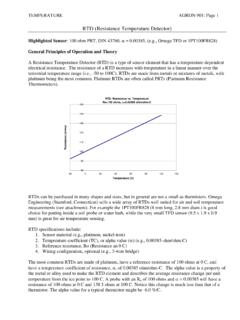
1 2003 Microchip Technology 1 MAN687 INTRODUCTIONThe most widely measured phenomena in the processcontrol environment is temperature. Common ele-ments, such as Resistance Temperature Detectors(RTDs), thermistors, thermocouples or diodes are usedto sense absolute temperatures , as well as changes intemperature. For an overview and comparison of thesesensors, refer to Microchip s AN679, Temperature-Sensing Technologies , DS00679. Of these technologies, the platinum RTD Temperature-Sensing element is the most accurate and stable overtime and temperature. RTD element technologies areconstantly improving, further enhancing the quality ofthe temperature measurement (see Figure 1). Typi-cally, a data acquisition system conditions the analogsignal from the RTD sensor, making the analogtranslation of the temperature usable in the application note focuses on circuit solutions thatuse platinum RTDs in their design.
2 Initially, the RTDtemperature- sensing element will be compared to thenegative temperature coefficient (NTC) thermistor,which is also a resistive Temperature-Sensing this forum, the linearity of the RTD will be presentedalong with calibration formulas that can be used toimprove the off-the-shelf linearity of the element. Foradditional information concerning the thermistor tem-perature sensor, refer to Microchip s AN685, Ther-mistors in Single Supply Temperature SensingCircuits , DS00685. Finally, the signal-conditioningpath for the RTD system will be covered withapplication Circuits from sensor to 1:Unlike thermistors, RTD Temperature-Sensing elements require current OVERVIEWThe acronym RTD is derived from the term Resis-tance Temperature Detector.
3 The most stable, linearand repeatable RTD is made of platinum metal. Thetemperature coefficient of the RTD element is is in contrast to the NTC thermistor, which has anegative temperature coefficient, as is shown graphi-cally in Figure 2. An approximation of the platinum RTDresistance change over temperature can be calculatedby using the constant / / C. This constant iseasily used to calculate the absolute resistance of theRTD at :Bonnie C. BakerMicrochip Technology Current Source <1 mAVOUTRTD, most popular elementis made using platinum ,typically 100 @ 0 CRTD T()RTD0 TRTD0 C +=where:RTD(T) is the resistance value of the RTD element attemperature (Celsius),RTD0 is the specified resistance of the RTD elementat 0 C and,T is the temperature environment that the RTD isplaced (Celsius).
4 Precision Temperature-Sensing with RTD CircuitsAN687DS00687B-page 2 2003 Microchip Technology 2:The temperature vs. resis-tance characteristics of the RTD sensing element is considerably different than the thermistor sen-sor element. The RTD sensing element has a positive temperature coefficient and is considerably more RTD element resistance is extremely low whencompared to the resistance of a NTC thermistorelement, which ranges up to 1 M at 25 C. Typicalspecified 0 C values for RTDs are 50, 100, 200, 500,1000 or 2000 . Of these options, the 100 platinumRTD is the most stable over time and linear the RTD element is excited with a current referenceat a level that does not create an error due to self-heat-ing, the accuracy can be C over its entire temper-ature range of -200 C to 800 C.
5 If a higher accuracytemperature measurement is required, the linearity for-mula below (Calendar-Van Dusen Equation) can beused in a calculation in the controller engine or be usedto generate a look-up linearity performance of a typical RTD is shown inFigure 3:The linearity error of the platinum RTD temperature sensor is small when compared to other sensors, such as the thermocouple and RTD element requires a current excitation. If themagnitude of the current source is too high, the elementwill dissipate power and start to self-heat. Consequently,care should be taken to insure that 1 mA of current isused to excite the RTD advantages and disadvantages of the RTDtemperature sensing element is summarized inTable 1:RTD TEMPERATURE sensing ELEMENT ADVANTAGES AND DISADVANTAGESRTD CURRENT EXCITATION CIRCUITFor best linearity, the RTD sensing element requires astable current reference for excitation.
6 This can beimplemented in a number of ways, one of which isshown in Figure 4. In this circuit , a voltage reference,along with two operational amplifiers, are used togenerate a floating 1 mA current ( C)Resistance ( ) 50050100 150 200 250 300 ThermistorRTDRTD T()RTD01 ATBT2100C T3CT4+ ++ =where:RTD(T) is the resistance of the RTD element at tem-perature,RTD0 is the specified resistance of the RTD elementat 0 C,T is the temperature that is applied to the RTD ele-ment (Celsius) and,A, B, and C are constants derived from resistancemeasurements at 0 C, 100 C and 260 Accurate and Stable Expensive SolutionFairly Linear to 4% CRequires CurrentExcitationGood RepeatabilityDanger of Self-HeatingLow Resistive ElementTemperature ( C)Temperature Error ( C) -100 0 100 200 300 400 500 600 700 800 2003 Microchip Technology 3AN687 FIGURE 4.
7 A current source for the RTD element can be constructed in a single-supply environment from two operational amplifiers and a Precision voltage is accomplished by applying a Precision volt-age reference to R4 of the circuit . Since R4 is equal toR3, and the non-inverting input to A1 is high-imped-ance, the voltage drop across these two resistors isequal. The voltage between R3 and R4 is applied to thenon-inverting input of A1. That voltage is gained by(1 + R2/R1) to the output of the amplifier and the top ofthe reference resistor, RREF. If R1 = R2, the voltage atthe output of A1 is equal to:EQUATIONThe voltage at the output of A2 is equal to:EQUATION This same voltage appears at the inverting input of A2and across to the non-inverting input of these equations, the voltage drop across thereference resistor, RREF, is equal to:EQUATIONThe current through RREF is equal to:EQUATIONThis circuit generates a current source that is ratio met-ric to the voltage reference.
8 The same voltage refer-ence can be used in other portions of the circuit , suchas the analog-to-digital (A/D) converter errors in the circuit will occur as a consequenceof the absolute voltage of the reference, the initial offsetvoltages of the operational amplifiers, the output swingof A1, mismatches between the resistors, the absoluteresistance value of RREF and the RTD element. Errorsdue to temperature changes in the circuit will occur as aconsequence of the temperature drift of the same ele-ments listed above. The primary error sources over tem-perature are the voltage reference, offset drift of theoperational amplifiers and the RTD SIGNAL-CONDITIONING PATHC hanges in resistance of the RTD element over tem-perature are usually digitized through an A/D conver-sion, as shown in Figure 5.
9 The current excitationcircuit, shown in Figure 4, is used to excite the RTDelement. with this style of excitation, the magnitude ofthe current source can be tuned to 1 mA or less byadjusting RREF. The voltage drop across the RTD ele-ment is sensed by A3, then gained and filtered by this circuit , a 3-wire RTD element is configuration minimizes errors due to wireresistance and wire resistance drift over MCP6021/2 MCP6021mARREF = k R2A1 RWRWRWA2 + + +R1R3R4 VREF= +()VREFVR4 () VOUTA12 VREFVR4 () ==where:VOUTA1 is the voltage at the output of A1 andVR4 is the voltage drop across VR3 =VRREFVOUTA1 VOUTA2 VRREF 2 VREFVR4 () VREFVR4 VR3 ()VRREF VREF===where:VRREF is the voltage across the reference resistor,RREF and,VR3 is the voltage drop across R3 IRTDVREF / RREF=AN687DS00687B-page 4 2003 Microchip Technology 5.
10 This circuit uses a RTD temperature-sensitive element to measure temperatures from -200 C to 600 C. The current generator circuit from Figure 4 excites the sensor. An operational amplifier (A3) is used to zero wire resistance error. A fourth amplifier (A4) is used to gain the signal and filter possible alias interference. A 12-bit converter (MCP3201) converts the voltage across the RTD to digital code for the 8-pin controller (PIC12C508).VREFVSS IN+IN1mARREF = k RA1RW1RW2RW2A2 RRRVREF = + +VINPT100(100 @ 0 C,RTD)R1=100 k R2 = 100 k CurrentGeneratorCircuitA31/4 MCP604 +R3A4C3C4R4R5R61/4 MCP604 +MCP3201 PIC12C508 2003 Microchip Technology 5AN687In this circuit , the RTD element equals 100 at 0 C. Ifthe RTD is used to sense temperature over its entirerange of -200 C to 600 C, the range of resistance pro-duced by the RTD would be nominally 23 to 331.