Transcription of Scaling and Biasing Analog Signals - symres.com
1 Scaling and Biasing Analog SignalsNovember 2007 IntroductionScaling and Biasing the range and offset of Analog Signals is a useful skill for workingwith a variety of electronics. Not only can it interface equipment with different inputand output voltage ranges together, it is also useful for designing circuits such asdiscrete transistor amplifiers. If you have a signal in one part of your circuit with aparticular voltage range and offset, and need to map it to another range and offset, Scaling and Biasing will help. Several methods are presented here, including passiveresistor designs and basic op amp begin, suppose you have an Analog input signalVin(t), whereVinis a time dependentvoltage.
2 Scaling and Biasing simply means computing a new signalVout(t):Vout(t) =s Vin(t) +b(1)where the parametersis called thescaleand the parameterbthebias. The goal is toconstruct an Analog electronic circuit that produces this linear transformation ofVintoVout. Effectively, the circuit will be an Analog computer for equation (1).In elementary algebra, the parameterssandbare called the slope and offset of astraight line. The wordsscaleandbiasas used in electronics are synonyms forslopeandoffset. Setting aside for the moment thatVinandVoutdepend ont, and focusinginstead onVoutas a function ofVin, equation (1) is the graph of a straight line.
3 Infact, given two (Vin, Vout) pairs on the straight line, we can computesandbwith:s= Vout/ Vin(2)b=Vout s Vin(3)where either one of the (Vin, Vout) pairs can be used to computeb. The parametersisdimensionless having the units (volts/volts), whilebhas the dimensions these equations in hand, specifying the input and output ranges is equivalentto specifyingsandb. For example, suppose you have a signal ranging from -100 to+100 volts, and you would like to map it into a (0,5) volt range. This is a commondata acquisition problem where a sensor may not match an A/D input range. In thisexample, since we have Vin= 200 and Vout= 5, equation (2) gives:s= Vout/ Vin= 5/200 = withVout= 0 whenVin= 100, equation (3) gives:b=Vout s Vin= 0 s ( 100) = 100 = the final transformation betweenVoutandVinfor this case would be:Vout= Vin+ testing various values in this equation you can verify it linearly maps voltages inthe range of (-100,100) into (0,5) volts.
4 Note that not only is the scale of the inputvoltage reduced by this particular transformation, negative inputs are mapped into apositive range as familiar with oscilloscopes already know Scaling and Biasing . Scopes typicallyhave one knobsto set the amplitude of the trace, and another knobbto translateit vertically up and down the display. Internally the scope has Scaling and biasingcircuits that can be set with the paper is aboutdesigningscaling and Biasing wouldlike to find a combination of resistors and other components to produce the trans-formation in equation (1). While not particularly difficult, the equations to computecomponent values are not trivial either.
5 We will even find mathematical techniquessuch as projective transformations play an interesting resistor circuitsTwo resistor dividers are a convenient starting point for Scaling and Biasing . Thissection reviews the basic Scaling divider, and then shows how to add a bias. We willfind even though two resistor circuits have limitations regarding their bias, they arestill useful for many applications. The next section,Three resistor circuits, will showhow to implement designs which are even more the following two resistor Scaling divider, whereVinis the input,Voutis theoutput, and (Ra, Rb) are the resistor values.
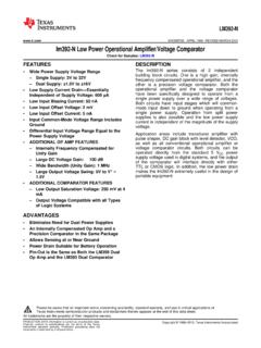
6 Note that the labelsVinandVoutcanbe confusing becauseVinis probably theoutputfrom some device on the left,andatthe same time is theinputto the divider. Don t confuse the meaning of the wordsinandoutwhen working with the equations below. This paper assigns labels from thedivider s point of = ARb = BSENSORA/DVoutVinFigure 1: Basic two resistor Scaling dividerUsing Kirchoff s and Ohm s laws, and assuming no loading onVout, the output voltageof this circuit is:Vout= [Rb/(Ra+Rb) ] Vin(4)The usual steps to derive this are: by Ohm s law, thecurrentthrough the seriescombination (Ra, Rb) is:Vin/(Ra+Rb) . Then, since this is the same current flowingthroughRb, the final output voltage is:Rb [Vin/(Ra+Rb)].
7 Deriving this equationshould become automatic if you are working with these types of circuits. Equation (4)can also be derived formally by applying Kirchoff s and Ohm s laws to each node andleg of the circuit and solving the resulting simultaneous that equation (4) can be written as:Vout= [ (B/A)/(1 + (B/A)) ] Vin(5)where two changes have been made. First, the resistor values have been denoted bycapital letters,A=RaandB=Rbto reduce the number of subscripts. We will followthat pattern in the rest of this this paper. Second, the top and bottom of equation(4) have been multiplied by 1/Ato showit is only the ratioB/Athat determinesthe output voltage.
8 Sometimes, ifBis much less thanA, it may even be possible toapproximate the output as (B/A)Vin, however here we will keep the equation exact soit is applicable to precision simple divider in Figure1is suitable for applications where only Scaling is equation (4) or (5) is the same as equation (1) withs=B/(A+B) andb= is to say it is a transformation with no bias or offset. As a specific example,suppose you have a sensor with an output range of 0 to 50 volts and wish to map thatinto a 0 to 5 volt range. ChoosingA= 90K ohms andB= 10K would scale the inputby 10/(10 + 90) = , and the (0,50) volt sensor would be divided down to (0,5)volts.
9 The circuit is:Vout(0,5)6 volt zener6 volt zenerB = 10KA = 90K Vin(0,50)Figure 2: Scaling (0,50) into (0,5) with no biasIf you build this circuit , be careful the high input voltage is never accidentally connecteddirectly toVout, because you might damage any downstream equipment. A 6 volt zeneracross the output would be a reasonable first step towards though it is only the ratioB/Athat determines the output in equation (4), alsokeep in mind thatthere are currentsflowing in the resistors. With a 90K and 10K4pair, a maximum current of 50v/100K = 1/2 milliamp will flow in the divider. This isgood, the resistors will not overheat, and hopefully the input source can provide thatamount of notuse a 9 ohm and 1 ohm resistor in the simple Scaling divider is fine for applications requiring only Scaling , it doesnot add any bias.
10 Negative voltages going into the divider come out negative, whileyou may require such voltages to be biased into the positive range. This can be doneby modifying the basic divider as shown in Figure3. The circuit is the same as thesimple Scaling dividerexceptthe end of resistorBis held at a nonzero voltage andnotat 3: Biased two resistor dividerThe output of the biased divider in Figure3is:Vout= [B/(A+B)] Vin+ [A/(A+B)] Vbias(6)With practice, equations like (6) can be written down at sight. Here is how: fromKirchoff s and Ohm s laws we knowVoutmust be alinear homogeneousfunction ofVinandVbias. Because of that we can solve forVoutwithVinandVbiasalternately setto zero and then add the partial results together to form the complete answer.