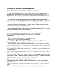
Transcription of Section 10 Chapter 9 - dmcpubs.com
1 Section 10 Chapter 97-89380NH24 Valve, Liter EngineCylinder Head Note: All coding used in the Liter and 9 Liter engine manuals are Cummins engine codes. These engine codes have no meaning to New Holland warranty codes and should only be used for procedure Valve, Liter EngineCylinder Head Page a7-89380 NHSection 10 Chapter 9 Issued 8-2001 Cylinder Head ContentsCrosshead (002-001) .. 2 Remove (002-001-002) .. 2 Inspect for Reuse (002-001-007) .. 2 Install (002-001-026) .. 2 Cylinder Head (002-004).
2 2 Preparatory (002-004-000) .. 2 Remove (002-004-002) .. 3 Clean (002-004-006) .. 4 Inspect for Reuse (002-004-007) .. 6 Install (002-004-026) .. 8 Injector Protrusion (002-022) .. 19 Measure (002-022-010) .. 19 Service 1 Cylinder Head .. 1 Valve, Cylinder Head (002-020) .. 12 Preparatory (002-020-000) .. 12 Disassemble (002-020-003) .. 13 Clean (002-020-006) .. 14 Inspect for Reuse (002-020-007) .. 14 Assemble (002-020-025) .. 17 Install (002-020-026) .. 1824 Valve, Liter EnginePage bCylinder Head7-89380 NHSection 10 Chapter 9 Issued 8-2001 THIS PAGE INTENTIONALLY LEFT BLANK24 Valve, Liter EngineService ToolsCylinder Head Page 17-89380 NHSection 10 Chapter 9 Issued 8-2001 Service ToolsCylinder HeadThe following special tools are recommended to perform procedures in this Section .
3 The use of these tools is shown in the appropriate pro-ceudre. Tool DescriptionTool IllustrationOEM 6414 Valve Spring CompressorUsed to remove and install valve Length GaugeUsed to measure capscrew free 6459 Gauge BlockUsed to measure the injector protrusion and valve recess in the cylinder head. 0 CNH299152 Engine Barring GearUsed to engage the flywheel ring gear to rotate the (002-001)24 Valve, Liter EnginePage 2 Cylinder Head7-89380 NHSection 10 Chapter 9 Issued 8-2001 Crosshead (002-001)Remove (002-001-002)Remove rocker lever cover and rocker levers.
4 Refer to procedures 003-011 and for Reuse (002-001-007)Check crossheads for cracks and/or excessive wear on rocker leverand valve tip mating (002-001-026)Install rocker lever assembly. Refer to Procedure 003-008. Install the rocker lever cover. Refer to Procedure Head (002-004)Preparatory (002-004-000)D WARNING DCoolant can be toxic. Keep away from children and pets. If not re-used, dispose of in accordance with local environmental WARNING DWait until the temperature is below 50 C [120 F] to avoid personalinjury from hot Valve, Liter EngineCylinder Head (002-004)Cylinder Head Page 37-89380 NHSection 10 Chapter 9 Issued 8-2001 Drain the coolant.
5 Refer to Procedure 008-018. Remove all water and heater hoses. Remove the intake manifold cover and intake heater (if equipped). Refer to Procedure 010-023. Remove the injector supply. Refer to Procedure 006-051. Remove the fuel connection tubes. Refer to Procedure 006-052. Remove the valve cover. Refer to Procedure 002-020. Remove the rocker levers. Refer to Procedure 003-008. Remove the injectors. Refer to Procedure 006-026. Remove the pushtubes. Refer to Procedure 003-008. Remove the fuel drain line.
6 Refer to Procedure 006-013. Remove the turbocharger. Refer to Procedure 010-033. Remove the exhaust manifold. Refer to Procedure (002-004-002)Remove drive belt. Refer to Procedure the fan hub this step if the fan hub assembly is not attached to the the cylinder head capscrews in the order Head (002-004)24 Valve, Liter EnginePage 4 Cylinder Head7-89380 NHSection 10 Chapter 9 Issued 8-2001D WARNING DThe component weighs 23 kg [50 lb] or more. To avoid personalinjury, use a hoist or get assistance to lift the Head Weight kg [165 lb]Remove the cylinder head and gasket from the cylinder (002-004-006)Clean the carbon from the injector nozzle the valves and springs.
7 Refer to Procedure the gasket material from all gasket surfaces on the block the build-up of deposits from the coolant passages. Excessivedeposits may be cleaned in an acid tank but the expansion plugs mustfirst be Valve, Liter EngineCylinder Head (002-004)Cylinder Head Page 57-89380 NHSection 10 Chapter 9 Issued 8-2001 Clean the cylinder head combustion deck with a Scotch-Brite , orequivalent, and diesel fuel or WARNING DWear protective eye covering while cleaning carbon deposits toprevent carbon deposits from the valve pockets with a high quality steelwire wheel installed in a drill or a die inferior quality wire wheel will lose steel bristles during operation.
8 Thus causing additional the cylinder head in hot soapy water with compressed CAUTION DDo not use caustic or acid solutions to clean the cylinder a petroleum-based solvent to clean the the capscrew thoroughly with a wire brush, a soft wire wheel, oruse a non-abrasive bead blast to remove deposits from the shank andthe Head (002-004)24 Valve, Liter EnginePage 6 Cylinder Head7-89380 NHSection 10 Chapter 9 Issued 8-2001 Inspect for Reuse (002-004-007)Straight Edge and Feeler GaugeCylinder Block Combustion Deck InspectUse a straight edge and feeler gauge to measure the overall flatnessof the cylinder overall flatness, end to end and side to side, must not mm [ in].
9 Inspect the combustion deck for any localized dips or imperfections. Ifpresent, the cylinder block head deck must be Head Cracks - Reuse GuidelinesThe reuse guidelines for a cylinder head with a crack extending fromthe injector bore to the intake valve seat are as follows:If the crack does not extend into the valve seat, the cylinder head is a crack extends into or through the valve seat, the cylinder headmust be repaired by replacing the valve seat a straight edge and a feeler gauge to inspect the cylinder headcombustion surface for Head FlatnessmminEnd to to Valve, Liter EngineCylinder Head (002-004)
10 Cylinder Head Page 77-89380 NHSection 10 Chapter 9 Issued 8-2001 Inspect the cylinder head capscrews for damaged threads, corrodedsurfaces, or a reduced diameter (due to capscrew stretching).Do not reuse cylinder head capscrews under the following conditions: Visible corrosion or pitting exceeds 1 sq cm [ sq in] in area. Example: acceptable is x mm [3/8 x 3/8 in] unacceptable is x mm [1/2 x 1/2 in] Visible corrosion or pitting exceeds mm [ in] in depth. Visible corrosion or pitting is located within mm [1/8 in] of the fillet or threads.