Transcription of Section 2.0 : Construction and Measurement of a Simple ...
1 Section : Construction and Measurement of a Simple Test Transmission LineBy Martin J. King, 07/05/02 Copyright 2002 by Martin J. King. All Rights 1 of 10 Section : Construction and Measurement of a Simple Test Transmission LineAfter deciding to use a Focal 8V 4412 mid-bass driver for my first transmissionline design, I started looking for a Simple enclosure in which to perform some testing tocorrelate my mathematical model. I came across a 48 long cardboard tube with a 7 inner diameter and wall thickness at my local hardware store.
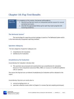
2 For five dollars I had atest transmission line enclosure. At one end of the tube I attached a nine inch squarepiece of thick plywood with a circular cutout that fit snuggly over the tube s outerdiameter. To secure this plywood flange, nails were driven outward through the tube intothe plywood at eight locations. The seam was sealed on both sides with silicon Focal 8V 4412 driver was mounted to the flange with a length of speaker cablethreaded out through the open end of the tube.
3 Figure shows the test transmissionline first test I ran, after breaking in the drivers, was to determine the Thiele /Small parameters of the Focal 8V 4412 using Liberty Instrument s Audiosuitemeasurement program LAUD. Table shows the results of these measurements alongwith the manufacturer s : Measured Thiele / Small Parametersof the Focal 8V Driver 1 Driver (10-7) sec/m5 Cmd (10-3) determining the Thiele / Small parameters for the Focal 8V 4412 drivers,Driver 2 was mounted in the test transmission line enclosure.
4 At this point the tube wascompletely empty. Three separate measurements were made. The first measurementwas of the impedance of the driver mounted in the tube. The second and thirdmeasurements were of the SPL directly in front of the driver and the SPL at the terminusof the tube. For the SPL measurements, the microphone was mounted as close to thedriver and terminus as possible to eliminate any reflections that might be generated fromthe floor or the baffle. The microphone was placed in front of the center of the driverdust cap and then out axially, along the centerline, from the terminus end of the : Construction and Measurement of a Simple Test Transmission LineBy Martin J.
5 King, 07/05/02 Copyright 2002 by Martin J. King. All Rights 2 of 10 The results of these measurements are shown in Figure The top plot is themagnitude and phase of the system impedance. The middle plot is the SPL and phaseof the woofer response. The bottom plot is the SPL and phase of the terminus plot contains a title describing the Measurement being presented. Each plot alsocontains the sampling rate and sample size used during the Measurement . For all of thefrequency response plots, ten measurements were averaged to get the final measurements were repeated after stuffing the tube with 100 gm, 200 gm,and 300 gm of Dacron Hollofil II fiber.
6 To stuff the tube, I made a 48 long cheese-clothcylinder and tied the ends closed with string. To add or remove stuffing, the cheese-clothcylinder was pulled out of the cardboard tube, untied, and unrolled flat. This techniquemade it easy to adjust the amount and type of stuffing in the test transmission , , and show the results of the measurements for 100 gm, 200 gm, and300 gm of Dacron Hollofil II stuffing. The format of the plots is the same as described forFigure studied the Measurement results to try and understand the behavior of the testtransmission line.
7 I started with the unstuffed measurements shown in Figure A lotcan be learned from these three plots. First, I calculated the quarter wavelength modesof the tube after including an end correction to the tube length corresponding to anunflanged exit boundary condition. The wavelength calculation is shown = mLeffective= + x = mf= c / (4 Leffective)= 67 Hzcair= 342 m/secTable shows the driver resonant frequency, the calculated tube quarter wavelengthfrequencies, and the measured system peaks from the plots in Figure.
8 Calculated and Measured Frequencies for the Unstuffed Test LineModeMeasured DriverResonance (Hz)Calculated TubeFrequencies (Hz)Measured SystemFrequencies (Hz)Driver34221/4 Wavelength67943/4 Wavelength2002145/4 Wavelength3343437/4 Wavelength4674759/4 Wavelength60159811/4 Wavelength734727 The first thing I noticed in Figure was a shift of the driver resonant frequencyin the impedance curve. The driver resonant frequency of approximately 34 Hz, asreported in Table , dropped to 22 Hz when the driver was mounted in the testtransmission line.
9 I attribute this change in frequency to an additional mass loading onthe speaker cone from the air moving in the transmission line. At this low frequency, theair in the transmission line acts like a solid slug of mass. Using the value of Mmd fromTable and the mass of air in the tube, the lowest system resonant frequency can beestimated and compared to the measured : Construction and Measurement of a Simple Test Transmission LineBy Martin J. King, 07/05/02 Copyright 2002 by Martin J. King. All Rights 3 of 10 Mmd= gmMair= air Vtube= kg/m3 ( m3)= gmfsystem= (1 / 2 ) {1 / [Cmd (Mmd + Mair)]}1/2= 20 HzI also noticed in Figure that the resonance peak I would associate with the wavelength mode of the tube had risen in frequency.
10 The peak in the impedance plot,and in the terminus SPL response plot, occurs at 91 Hz versus the calculated value of67 Hz. However, in the driver SPL response plot, a sharp null is evident at 70 Hz. Thissharp null almost matches the calculated wavelength frequency of 67 Hz. The drop inthe driver resonant frequency and the rise in the first tube resonant frequency is identicalin behavior to what is seen in the response plots for a ported box then started looking at Figures , , and that show the samemeasurements as Figure but for three different amounts of Dacron Hollofil II the amount of stuffing in the test line into a mass per unit volume yields thefollowing gm= lb/ft3200 gm= lb/ft3300 gm= lb/ft3 These values span the stuffing density I anticipated using in my final designs.