Transcription of SECTION 5 - RETAINING WALLS - Caltrans
1 bridge DESIGN SPECIFICATIONS AUGUST 2004 SECTION 5 - RETAINING WALLS Part A General Requirements and Materials GENERAL RETAINING WALLS shall be designed to withstand lateral earth and water pressures, the effects of surcharge loads, the self-weight of the wall and in special cases, earth quake loads in accordance with the general principles specified in this SECTION . RETAINING WALLS shall be designed for a service life based on consideration of the potential long-term effects of material deterioration on each of the material compo nents comprising the wall. Permanent RETAINING WALLS should be designed for a minimum service life of 50 years.
2 Temporary RETAINING WALLS should be designed for a minimum service life of 5 years. The quality of in-service performance is an important consideration in the design of permanent RETAINING WALLS . Permanent WALLS shall be designed to retain an aestheti cally pleasing appearance, and be essentially mainte nance free throughout their design service life. The Service Load Design Method shall be used for the design of RETAINING WALLS except where noted otherwise. WALL TYPES RETAINING WALLS are generally classified as gravity, semi-gravity (or conventional), non-gravity cantilevered, and anchored.
3 Gravity WALLS derive their capacity to resist lateral loads through dead weight of the wall. The gravity wall type includes rigid gravity WALLS , mechanically stabilized earth (MSE) WALLS , and prefabricated modular gravity WALLS . Semi-gravity WALLS are similar to gravity WALLS , except they rely on their structural components to mobilize the dead weight of backfill to derive their capacity to resist lateral loads. Non-gravity cantilevered WALLS rely on structural components of the wall partially embedded in foundation material to mobilize passive resistance to resist lateral loads.
4 Anchored WALLS derive their capacity to resist lateral loads by their structural components being restrained by tension elements con nected to anchors and possibly additionally by partial embedment of their structural components into founda tion material. The anchors may be ground anchors (tiebacks), passive concrete anchors, passive pile an chors, or pile group anchors. The ground anchors are connected directly to the wall structural components whereas the other type anchors are connected to the wall structural components through tie rods. Within the wall types above, many of the RETAINING wall systems available are proprietary.
5 Their use requires appropriate contrac tual requirements. See Figures through for examples. Selection of Wall Type Selection of appropriate wall type is based on an assessment of the design loading, depth to adequate foundation support, presence of deleterious environmen tal factors, physical constraints of the site, cross-sectional geometry of the site both existing and planned, settle ment potential, desired aesthetics, constructibility, main tenance, and cost. Rigid Gravity and Semi-Gravity WALLS Rigid gravity WALLS may be constructed of stone ma sonry, unreinforced concrete, or reinforced concrete.
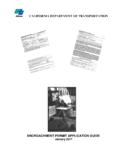
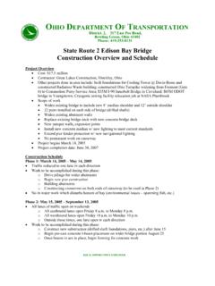
6 These WALLS can be used in both cut and fill applications. They have relatively narrow base widths. They are generally not used when deep foundations are required. They are most economical at low wall heights. SECTION 5 RETAINING WALLS 5-1 bridge DESIGN SPECIFICATIONS AUGUST 2004 Face Panels Soil Reinforcement MSE Wall with Precast Concrete Face Panels Batter 1:6 Precast Concrete Crib Wall Figure Typical Gravity RETAINING WALLS Semi-gravity cantilever, counterfort and buttress WALLS are constructed of reinforced concrete. They can be used in both cut and fill applications.
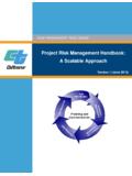
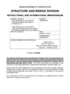
7 They have relatively narrow base widths. They can be supported by both shallow and deep foundations. The position of the wall stem relative to the footing can be varied to accommodate right-of-way constraints. These WALLS can support soundwalls, sign structures, and other highway features. They can accommodate drainage structures and utilities and span existing drainage structures and load sensitive Reinforced Concrete Cantilever Wall Figure Typical Semi-Gravity RETAINING WALLS utilities. They are most economical at low to medium wall heights. Due to the rigidity of rigid gravity WALLS and semi-gravity WALLS they should only be used where their foun dations can be designed to limit total and differential settlements to acceptable values.
8 Non-Gravity Cantilevered WALLS Non-gravity cantilevered WALLS are constructed of vertical structural members consisting of partially em bedded soldier piles or continuous sheet piles. Soldier piles may be constructed with driven steel piles, treated timber, precast concrete or steel piles placed in drilled holes and backfilled with concrete or cast-in-place rein forced concrete. Continuous sheet piles may be con structed with driven precast prestressed concrete sheet piles or steel sheet piles. Soldier piles are faced with either treated timber, reinforced shotcrete, reinforced cast-in place concrete, precast concrete or metal elements.
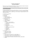
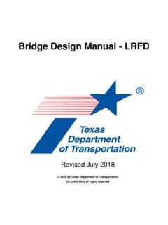
9 This type wall is suitable for both cut and fill applica tions but is most suitable for cut applications. Because of the narrow base width of this type wall it is suitable for 5-2 SECTION 5 RETAINING WALLS bridge DESIGN SPECIFICATIONS AUGUST 2004 situations with tight space constraints or right-of-way constraints. Discrete Vertical Wall Elements Soldier pile with timber lagging Continuous Vertical Wall Elements Steel Sheet Piles Figure Typical Non-Gravity Cantilevered RETAINING WALLS This type wall depends on passive resistance of the foundation material and the moment resisting capacity of the vertical structural members for stability, therefore its maximum height is limited by the competence of the foundation material and the moment resisting capacity of the vertical structural members.
10 Because this type wall depends on the passive resistance of foundation material, it should not be used where it is likely that foundation material will be removed in front of the wall during its service life. The economical height of this type wall is generally limited to a maximum height of 20 feet or less. Anchored WALLS Anchored WALLS are typically composed of the same elements as non-gravity cantilevered WALLS (Article ), but derive additional lateral resistance from one or more levels of anchors. The anchors may be ground anchors (tiebacks) consisting of drilled holes with grouted in prestressing steel tendons extending from the wall face to an anchor zone located behind potential failure planes in the retained soil or rock mass.