Transcription of Section 55 Chapter 9 - dmcpubs.com
1 Section 55. Chapter 9. INSTRUMENT CLUSTER (ICU2). TG SERIES JAW 137300 AND AFTER. Programming and Fault Codes Special Note: Only Fault Codes which have changed due to the Later Version ICU (ICU2) are included in this Section . If the tractor has the Later Version ICU, use the schematic foldouts in this Section with the early version fault code troubleshooting. Section 55 - INSTRUMENT CLUSTER (ICU2) - Chapter 9. TABLE OF CONTENTS. INSTRUMENT CLUSTER (ICU2) .. 9-4. Warning/Fault Displays .. 9-6. Critical Warning Displays - Level 1 .. 9-6. Non-Critical Displays - Level 2 .. 9-7. Deluxe Monitor Display (If Equipped) .. 9-11. INSTRUMENTATION PROGRAMMING .. 9-12. General Information .. 9-12. Operation Setup .. 9-12. RADAR CALIBRATION.
2 9-16. Controller Configuration .. 9-19. Configuration/Calibration Mode .. 9-20. FAULT CODE RETRIEVAL .. 9-24. PASSIVE TERMINATOR BENCH TEST .. 9-26. SYMPTOM BASED FAULTS - NO FAULT CODES .. 9-27. STANDARD INSTRUMENTATION CONTROLLER FAULT CODES .. 9-31. ARMREST CONTROLLER CALIBRATION .. 9-52. General Information .. 9-52. Entering Armrest Calibration .. 9-53. Hitch Menu .. 9-53. Throttle Menu .. 9-55. Remote Valve Menu .. 9-55. ARM MFD .. 9-58. ARM TRANS .. 9-58. View Menu .. 9-59. Exit Calibration .. 9-60. ARMREST CONTROLLER FAULT CODES .. 9-61. TRANSMISSION CONTROLLER CONFIGURATION AND CALIBRATION .. 9-62. Important General Information .. 9-62. When Calibration is Required .. 9-62. To access these menus: .. 9-63. Trans View Mode.
3 9-64. Trans Setup Mode .. 9-71. Clutch Calibration Procedure .. 9-72. Calibration Error Messages .. 9-77. Gear Default Mode .. 9-77. TRANSMISSION CONTROLLER FAULT CODES .. 9-90. 9-2. Section 55 - INSTRUMENT CLUSTER (LATER VERSION) - Chapter 9. REMOTE HYDRAULICS CONTROLLER CALIBRATION .. 9-94. Requirements For Calibration .. 9-94. Aux Set Main Menu .. 9-94. Aux View Menu .. 9-95. Aux Adjust Menu .. 9-97. Aux Setup Menu .. 9-98. Aux Cal Menu .. 9-99. Calibration Process .. 9-99. If Equipped with MegaFlow .. 9-100. REMOTE (AUX) CONTROLLER FAULT CODES .. 9-102. HITCH CONTROLLER CALIBRATION .. 9-104. Setup Process .. 9-104. Requirements For Calibration .. 9-104. Hitch Setup Main Menu .. 9-104. Hitch Calibration Menu .. 9-105. Hitch Setting Menu.
4 9-110. Hitch View Menu .. 9-112. HITCH CONTROLLER FAULT CODES .. 9-113. PTO CONTROLLER CONFIGURATION .. 9-116. General Information .. 9-116. PTO Main Menu .. 9-116. PTO Speed Menu .. 9-117. View Menu .. 9-117. SYMPTOM BASED FAULTS - NO FAULT CODES .. 9-119. PTO CONTROLLER FAULT CODES .. 9-121. SCHEMATIC FOLDOUTS .. 9-125. Data Bus sections 12 through 18 .. 9-125. Instrument Cluster .. 9-127. Transmission .. 9-129. Transmission Control System .. 9-131. PTO Controller System .. 9-133. Hitch Control System (EDC) .. 9-135. Auxiliary Control System .. 9-137. Seat .. 9-139. 9-3. Template Name: OML_2_col Rac 0-00000. Template Date: 2001_03_06. Section 55 - INSTRUMENT CLUSTER (ICU2) - Chapter 9. INSTRUMENT CLUSTER (ICU2). The instrument cluster is mounted on the front right hand cab post.
5 The instrument cluster will automatically monitor various operating systems and functions on your tractor. The condition of the monitored systems is indicated by analog gauges, LED indicator lamps and LCD text displays. The instrument cluster displays tractor performance information and provides audible alarm conditions which are important to the operation of the tractor and implement system. When the key switch is turned to the ON position, the tractor instrumentation will do a self check of all monitored systems. All indicator lamps and display screens will energize for 3 seconds. Before starting the tractor, make sure all systems are operating. If any system is not operating, contact your dealer. See your operator's manual for further information regarding the instrument cluster.
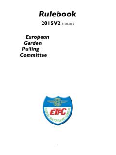
6 MT04M007. 1. PROGRAMMABLE DISPLAY - This display is us e d to c o mmun ic a te i nfo r ma ti on o r tex t messages. Each message is associated with a 1. graphic icon to identify the vehicle system. Normally, engine hours are displayed at the top of the display. If the RESET is pressed and held for 2 seconds, old hours will be displayed. When the PTO is engaged the PTO icon and the speed will override the engine hour display. Auto 2. auxiliary (if equipped) display will also override the engine hour display, but not the PTO display. Text messages will override entire display when in programming mode or when warnings occur. MT04M021. The Standard Programmable Display provides p e r fo r m a n c e i n fo r m a t i o n o n t h e e n g i n e , transmission and hydraulic systems as well as fault warnings when they occur.
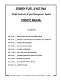
7 The Deluxe Programmable Display provides additional perfor mance infor mation on the engine, transmission and hydraulic systems, as well as fault warnings when they occur. 2. KEYPAD - The keypad is used to access, modify, clear or set limits to the information within the display or to clear fault warnings from the display. The Standard (six key) and Deluxe (twelve key). keypad functions are as follows: 9-4. Section 55 - INSTRUMENT CLUSTER (ICU2) - Chapter 9. STANDARD KEYPAD. Key Function PROG 1 - To enter setup mode and to select parameters within setup and diagnostics mode. 2 - To enter display monitor adjustment menu for ICU data screen order, backlighting and contrast. INCR To increase value of displayed number or (Up Arrow) scroll up through information screens.
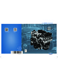
8 DECR To decrease value of displayed number or (Down Arrow) scroll down through information screens. RI05D001. RESET Used to reset warning faults, programming modes and diagnostic modes. DIAG To enter diagnostics mode and display ENGINE hours. AUTO Function not available. DELUXE KEYPAD. Key Function A To toggle menu screen selection. B To toggle menu screen selection. TIMER* To display remote hydraulic timer screen. PROG 1 - To enter setup mode and to select parameters within setup and diagnostics mode. 2 - To enter display monitor adjustment menu for ICU data screen order, backlighting and contrast. INCR To increase value of displayed number or (Up Arrow) scroll up through information screens. RESET Used to reset warning faults, programming modes and diagnostic modes.
9 DIAG To enter diagnostics mode and display ENGINE hours. DECR To decrease value of displayed number or (Down scroll down through information screens. Arrow). RI05D004. AUTO Function not available. SLIP To display percent slip when equipped with radar. AREA To display Area Information screen or to edit implement width and accumulated area. % To display % power, % slip and fuel rate. POWER**. *This function is not available on tractors equipped with stepper motor AUX valves. **This function is not available on tractors equipped with mechanical fuel injection pumps. 9-5. Section 55 - INSTRUMENT CLUSTER (ICU2) - Chapter 9. WARNING/FAULT DISPLAYS. The programmable display will notify the operator when there is a problem with the engine, transmission, hydraulics or other operational systems that require corrective action.
10 The warnings include an audible alarm, one or more indicator lights and text in the programmable display. The warnings are divided into four levels of importance and descending order of priority within each level. In the case of multiple faults or warnings the higher level or higher priority within a level will be the warning displayed. The following tables are listings of the icons, warning text, problems and corrective action required in order of importance and priority. Critical Warning Displays - Level 1. Level 1 critical warnings require immediate attention or there will be serious damage to the tractor. When a critical fault occurs, the red stop light, the amber warning light and the audible alarm will flash continuously and a text message will appear in the lower display.